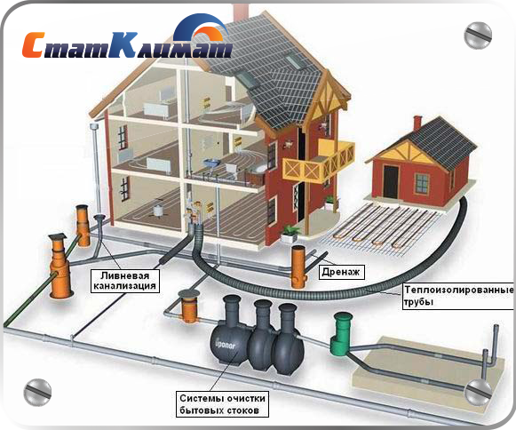
From internal pipelines, drains are transported by external ...
These recommendations, which are the generalized experience of civil aviation enterprises and other industries in cleaning floors and stained-glass windows, were developed with the aim of further improving the technology of mechanized cleaning of floors and stained-glass windows.
The recommendations are intended for employees of operating enterprises and designers of airports, air travel agencies and other similar types of passenger buildings.
MINISTRY OF CIVIL AVIATION
State Design and Research and Research Institute
Aeroproject
MOSCOW
These Recommendations are developed on the basis of studies conducted by the GPI and NII GA Aeroproject jointly on Soyuzdorniya, and as a result of a generalization of application experiencerep metalizing mastics at civil aviation airports.
In compiling the Recommendations, the following documents were used: “Technical conditions TU 6-05-1816-77. Compounds epoxy brands UP-5-122AT and UP-5-122AT-1 ", 1977, as amended from 1981;" Recommendations on tools in the technology for pouring cracks and seams of airfield coatings ", Moscow, GPI and NII GA Aeroproject, 1976; "Guide to the organization and technology of repair of airfields without interruption of flight operation" M., GPI and NIIGA Aeroproject, 1979; "Factory rules for the filling of wires ESP 007502" Prague, 1971.
1.1. The performance and durability of the sealing materials used to fill the furrows of the power supply wires depend on climatic factors and on the nature of the effect of the gas jets of the jet engines of the aircraft on the coating.
1.2. Sealing material must ensure that the furrow is watertight and protect the cable from damage. The assessment of the suitability of existing mastics for sealing the furrows of the power wires of the “Candle-3” and ID-2 in-depth type fires was made on the basis of materials for examining artificial coatings and experience gained from operating aerodrome coatings.
1.3. All work on laying wires in the furrows and filling them with sealing material, it is necessary to conduct dry and clear weather at an ambient temperature of at least + 5 ° C.
1.4. Fill fillers in aerodrome coatings should not change their properties after short-term (up to 1.5 min) exposure to temperatures up to + 250 ° С.
1.5. Furrow fillers should have sufficient cordon with concrete and asphalt concrete, not crack under the influence of low temperatures and maintain their elastic properties during operation.
1.6. Furrow fillers must have sufficient deformative and strength properties within the temperature range from -40 ° С to + 80 ° С, as well as resistance to the action of anti-icing reagents.
1.7. The viability of freshly prepared aggregate should be at least 4 hours. Sealant approval should take place no more than 7-10 days. The sealing material should not stick to the pneumatics of aircraft.
2.1. To fill the furrows of the power wires of cement-concrete and reinforced concrete coatings, the UP-5-122AT compound (TU6-05-1816-87) and the mastic produced by Czechoslovakia EP0KSI-15 are used.
The UP-5-122AT compound, produced by the domestic industry, is a product of combining UP-5-122A grade epoxy resin, thiol plasticizer (GOST 12812-72), polyethylene polyamine hardener (TU 6-02-594-75) and UP- accelerator 606/2 (T U 6-09-4136-75).
2.2. Curable compound UP-5-122AT is characterized by high deformability, good adhesion to concrete, sufficient water, heat, and frost resistance.
Compound UP-5-122AT is a homogeneous viscous liquid of yellow or red-brown color without foreign inclusions; it has the following physical and mechanical properties;
2.3. The compound should be prepared at the place of work, immediately before filling the furrows, by mixing the components in a cold state, weighing no more 5.0 kg, since a higher mass cannot achieve uniform mixing.
Since the compound at an air temperature above + 25 °C quickly grasps and difficulties arise in filling the furrows, then the prepared compound is not subject to storage.
2.4.Dosage of the components of the UP-5-122AT compound in the field should be carried out by volume.
2.5. In some cases, in the absence of sealing materials based on epoxy resins in cement concrete and reinforced concrete coatings, mastics based on a rubber-bitumen binder may be recommended for sealing grooves of power wires. In this case, after cleaning the walls, the grooves are primed with a thin layer of a solution of RBV in gasoline in a ratio of 1: 1.
2.6. Rezinobitumnaya binder (TU-21-27-41-75) is produced by the industry in a ready-made form, is a homogeneous mixture obtained from crumb rubber, bitumen, coumaron resin B and D, motor oil Ak-15 and plasticizing additives (polyisobutylene P-200) or without it.
Resin-bituminous binders are produced in three grades: RBV-25, RBV-35, RBV-50. The composition of RBV-25 is recommended for use inIV and V, RBV-35 in III and IV and RBV-50- in I and II climatic zones. Bituminous mastic should be used inII g III climatic zones.
2.7. For the preparation of polymer-bitumen mastics, bitumen BND 90/130 - 100 parts by hour is used; divinyl styrene thermoplastic elastomer (dry matter) - 26 hours; condensate "Vuktyl" - 12 including; asbestos flour - 28 including and Portland cement M400 - 28 parts by hour
2.8. The main physical and mechanical properties of the mastics RBV and polymer bitumen are given in the table.
| Brands of sealing materials | Tensile strength, MPa | Relative extension, % | Adhesion to concrete, MPa | Fragility temperature, °C |
| BMTV-1 | 0,6 - 0,9 | |||
| RBV-25 | 0,25 - 0,50 | |||
| RBV-35 | 0,25 - 0,50 | |||
| RBV-50 | 0,25 - 0,50 |
2.9. The technology for the preparation of mastics is given in the “Recommendations on the means and technology for filling cracks and seams of airfield coatings”.
2.10. Filling the furrows with RB masticB should be carried out at a temperature of sealant 170-200 ° C using a manual grout developed by GPI and NII GAA er po n po project, and in the absence of it, manually.
2.11. Estimated consumption of RBV mastic per 100 linear meters. m furrows are about 50 kg, mastics UP-5-122AT- about 25 kg. The approximate consumption of UP-5-122AT-1 mastic for fixing one fire, depending on its design, is from 3 to 5 kg.
3.1. Cutting the grooves of the power wires is carried out in accordance with the design of the DS-133 cutter. The maximum cutting depth is 80 mm.
3.2. Before laying the wires, the grooves of the furrows must be thoroughly cleaned, followed by blowing with a stream of compressed air. The walls of the furrows must be filled before filling. to be dry. The electric wires must not extend to the surface of the coating. For this purpose, rubber rollers 5 cm long are laid on the wires every 80 cm. The grooves of the furrows must be in the correct shape, without chips and cracks.
3.3. The recommended groove width for laying the CE-4 cable is 11 mm, for laying the KRZ cable - 13 mm. The depth of the cut furrow is set depending on the number of wires and mastic used and varies from 30 to 70 mm. The order of filling the groove from bottom to top:
5mm sand, wires (from 2 to 8), 10mm sand, UP-5-122AT mastic;
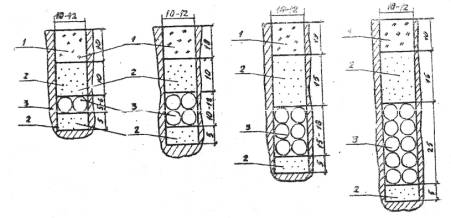
The minimum casting depth of the UP-5-122AT compound in cement concrete and reinforced concrete coatings is 10 mm. Minimum furrow fill depth with RB masticB in asphalt-concrete and cement-concrete coatings of 30 mm. In fig. Figures 1 and 2 show the patterns for filling the furrows in cement concrete and asphalt concrete coatings with various mastics.
3.4.To reduce the possible swelling with mastic, the RBB is first filled with 2/3 of the furrow depth, and after cooling to a temperature of 60-80 ° C, the furrow is completely filled. Excess mastic is removed with a heated scraper.
3.5. At the intersection of the grooves of the power supply wires of the lights of an in-depth type with temperature seams, recesses should be made from 50 to 80 mm, depending on the number of wires. Wires should be embedded in perchlorovinyl tubes, filled with dried and sifted sand, and filled with RBV mastic. The scheme of laying pipelines at the intersection of furrows with temperature seams is shown in Fig. 3.
Fig. 1. The scheme of filling the grooves in cement concrete coatings when protecting the cable with epoxy-based mastics: I - epoxy based mastic; 2 - fine sand; 3 - cable
Note . The diameter of the CE-4 cable is 5 mm, and the KP3 cable is 6 mm.
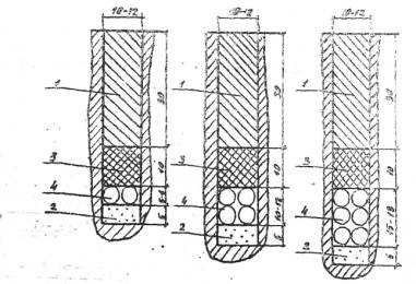
Fig. 2. The scheme of filling the furrows when protecting the power cable with RBV mastic: I - mastic RBV; 2 - fine-grained sand; 3 - oiled tow; 4 - cable
Note . The diameter of the CE-4 cable is 5 mm, and the KP3 cable is 6 mm.
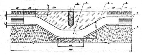
Fig. 3. Layout of wires at the intersection of the furrow-temperature seam:
1 - perchlorovinyl tube Ø25 or 32 mm dependingon the number of wires; 2 - mastic RBV; 3 - filling mastic; 4 - sand; 5 - concrete reinforced; 6 - temperature seam
4.1. In the process of preparing mastic, it is necessary to control:
weight dosage of the components of the compound;
uniform mixing throughout the mass of mastic;
temperature heating mastic RBV and BMTV.
4.2. Heat resistance of the mastic is checked after completion the formation of the passage of the heat engine in the mode of its operation in the winter.
Melting and blowing of mastic in a furrow is not allowed.
4.3. To ensure reliable sealing and to protect the wires from damage, it is necessary to carry out systematic monitoring of the state of the mastic on the furrow. In areas where the mastic has peeled off or has been chipped, the destroyed area should be cleaned and then filled with mastic.
5.1. The components of the compound are stored in hermetically sealed containers in a normal warehouse at a temperature not above + 30 ° C in conditions ensuring the safety of the product and packaging.
5.2. The compound is prepared immediately before use from the starting components. Freshly prepared compounds cannot be stored.
5.3. The warranty period of storage of individual components is determined by the current regulatory and technical documentation and is: for epoxy-modified resin - 6 months; hardener polyethylene polyamine - 6 months; accelerator brand UP-606/2 - 6 months; thiokol - 3 years.
5.4. RBV is produced by the manufacturer, transported and stored in pieces of pieces weighing 10-15 kg or in paper bags weighing up to 35 kg.
5.5. During storage and transportation, the sealant must be protected from exposure to sunlight and moisture.
6.1. Uncured compound UP-5-122AT and its constituent components in direct contact have an irritating effect on human skin, manifested in the form of eczema and dermatitis. Therefore, all workers involved in the preparation and use of mastics should be provided with protective clothing.
6.2. All operations on preparation of the UP-5-122AT compound should be performed in open air.
6.3. Sprays of resin, hardener or plasticizer should be immediately removed with a dry swab, followed by treatment of the skin with alcohol and washing with warm water.
6.4. Components of epoxy compounds (resin, thiokol, hardener) burn when introduced into the source of fire. Extinguishing media are water, steam and carbon dioxide fire extinguishers.
In place of the mastic heating work, fire extinguishing means (fire extinguisher, box with sand).
6.5. For the preparation, transportation and use of RBV mastics, it is allowed to use only serviceable mechanisms and devices.
6.6. When heating the sealing material, it is necessary to monitor the operation of fuel nozzles.
6.7. It is necessary to timely clear boilers and furnaces from soot.
6.8. Care must be taken when pouring hot mastic from the boiler into the machine for filling joints.
6.9. When heating the sealing material is prohibited:
reheat the material in boilers with open lids;
work with a faulty fuel supply system;
reload molten mass into boilers;
exceed the temperature of the heated material (180 ± 5 °C)
6.10. If rubber-bituminous mastic gets on the open surface of the skin, it must be removed with a clean rag moistened with gasoline or kerosene, then rinse with water.
Labor safety at the objects of urban construction and economy when using cranes and hoists.
Educational, practical and reference manual.
Authors: Roitman V.M., Umnyakova N.P., Chernysheva O.I.
Moscow 2005
3.1.3. Longitudinal binding of tower cranes.
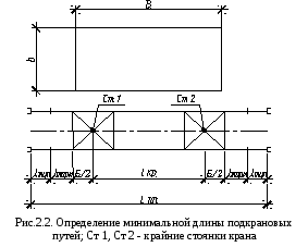
The definition of the extreme stops of the crane (Fig. 2.1.) Is carried out in the following order:
From the extreme corners of the external dimension of the building, from the side opposite the tower crane, serrations are made with a compass solution corresponding to the maximum reach of the crane's boom L max (Art. 1 and Art. 2);
From the middle of the internal contour of the building - with a compass solution corresponding to the minimum outreach of the crane L min (Art. 3 and Art. 4);
From the center of gravity of the heaviest elements - a compass solution corresponding to a specific boom reach L 1 according to the cargo characteristics of the crane (Art. 5 and Art. 6).
Extreme serifs determine the position of the center of the crane in the extreme position.
According to the found extreme parking sites of the crane, the length of the crane paths is determined (Fig. 2.2.):
L PP \u003d l KR + B + 2l TORM + 2l TUP ,
where L PP - the length of the crane ways, m; l KR - the distance between the extreme stops of the crane, determined according to Fig.2.1., m; B - crane base, determined by reference books (Appendix A), m; l TORM - the value of the stopping distance of the crane, taken at least 1.5 m; l TUP - the distance from the end of the rail to the dead ends, equal to 0.5 m
The determined length of the crane tracks is adjusted upwards taking into account the multiplicity of the half link length, i.e. 6.25 m. The minimum allowable length of the crane tracks is two links (25 m).
Auditory lessons - 4 hours.
Lesson purpose. Acquaintance with the methodology for calculating the hazardous area of \u200b\u200bconstruction cranes, the acquisition of design skills for construction plans.
Determine the size and place the fence of the construction site, given the compactness of the construction plan. Determine the location of the tower crane for the construction of a multi-storey building, calculate the danger zone. If necessary, set the range of the mounting crane.
3.1. Initial data.
Table 3.1 - Task for the practical training №3
|
options |
Dimensions of the building, m |
Building height, m |
Maximum design dimension, m |
Compact construction plan |
Having the initial data on the dimensions of the facility being built, select the number of cranes and organize the crane's workplace.
When choosing a crane workstation (parking), it is necessary to analyze various options for its placement and movement, as well as its technical capabilities, depending on the characteristics of the structures to be lifted and the dimensions of the building being erected.
The number of cranes depends on the construction deadlines and the configuration of the buildings.
For the construction of multi-storey buildings, as a rule, tower cranes are installed on one side (opposite the exits).
Cross-linking to the building of tower cranes with a lower counterweight location is determined by the dimensions of the turntable, increased by a distance of 0.7 m. The attachment of an attached crane depends on the dimensions of its support, for example, the concrete foundation to which the crane is attached using anchor bolts; take 2.5 - 3.5 m.
Labor safety at the objects of urban construction and economy when using cranes and hoists.
Educational, practical and reference manual.
Authors: Roitman V.M., Umnyakova N.P., Chernysheva O.I.
Moscow 2005
3.1.2. Cross anchoring of cranes.
B \u003d R max + l without (3.3)
where:
R max - the maximum radius of rotation of the platform (or other protruding part) of the crane (m);
From internal pipelines, drains are transported by external ...
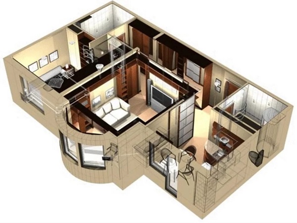
Each apartment, like every family, has its own characteristics, so it is difficult ...