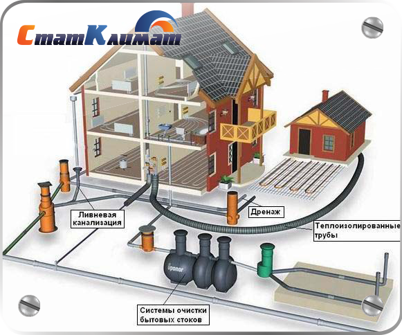
From internal pipelines, drains are transported by external ...
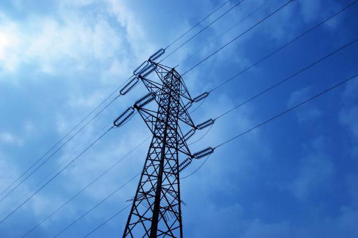
ELECTRICITY
ELECTRICITY, a form of energy existing in the form of static or moving ELECTRIC CHARGES. Charges can be positive or negative. Identical charges repel, opposite charges attract. The forces of interaction between charges are described by the PENDANT LAW. When the charges move in a magnetic field, they are affected by magnetic force and, in turn, create an oppositely directed magnetic field (FARADAY LAWS). Electricity and MAGNETISM represent various aspects of the same phenomenon, ELECTROMAGNETISM. The flow of charges forms an ELECTRIC current, which in the conductor is a stream of negatively charged ELECTRONS. In order for an electric current to occur in a CONDUCTOR, an ELECTRIC MOVING FORCE or a POTENTIAL BETWEEN the ends of the conductor is necessary. A current that moves in only one direction is called constant. Such current is created when the BATTERY is the source of the potential difference. A current that changes direction twice per cycle is called a variable. The source of this current are central networks. The unit of measurement of current is AMPER, the unit of charge is PENDANT, ohm is the unit of resistance, and volt is the unit of electromotive force. The main means for calculating the parameters of the electric circuit are the LAW OF OMA and the LAWS of the KIRCHHOF (on the summation of the voltage and current in the circuit). see also ELECTRICITY, ELECTRONICS.
Electric energy can be obtained by induction in a generator; voltage in the primary winding creates an alternating current in the external circuit. The presence of an inductance or capacitance (or both) leads to a phase shift (A) between voltage V and current I. The figure shows that the capacitance caused a phase shift of 90 °, resulting in an average power value of 0, although the power curve no still has the form of a sinusoid. The power reduction P caused by the phase displacement is called the power factor. If the three phases of the alternating current are offset between each other by 120 °, then the sum of their current or voltage values \u200b\u200bwill always be zero (V). Such three-phase currents are used in short-circuit asynchronous electric motors with a rotor (C). In this design, there are three electromagnets rotating in the created magnetic field. Alternating current is also produced in closed (D) and open (E) oscillatory circuits. The high frequency electromagnetic waves used in some communication systems are PRODUCED by TEKIM1 circuits.
Scientific and technical encyclopedic dictionary.
Synonyms:- (from the Greek. elektron amber, as amber attracts light bodies). The special property of some bodies, which manifests itself only under certain conditions, for example. with friction, heat, or chemical reactions, and detected by the attraction of lighter ... ... Dictionary of foreign words of the Russian language
ELECTRICITY, electricity, pl. no, cf. (Greek: elektron). 1. The substance that underlies the structure of matter (physical). || The peculiar phenomena accompanying the movement and movement of particles of this substance, the form of energy (electric current, etc.) ... Explanatory Dictionary of Ushakov
The totality of phenomena due to the existence, motion and interaction of charged bodies or particles of carriers of electric charges. The connection of electricity and magnetism, the interaction of stationary electric charges is carried out ... ...
- (from the Greek. elektron amber) the totality of phenomena in which the existence, movement and interaction (through the electromagnetic field) of charged particles is detected. The doctrine of electricity is one of the main branches of physics. Often under ... ... Big Encyclopedic Dictionary
Electricity is a stream of particles moving in a certain direction. They have a certain charge. In another way, electricity is the energy that is produced by movement, as well as the lighting that appears after energy is received. The term was introduced by the scientist William Gilbert in 1600. When conducting experiments with amber, the ancient Greek Thales discovered that a charge was acquired by a mineral. "Amber" in Greek means "electron." Hence the name came from.
Thanks to electricity, an electric field is created around current conductors or bodies with a charge. Through it, it becomes possible to act on other bodies, which also have a certain charge.
Everyone knows that charges are positive and negative. Of course, this is a conditional division, but according to the prevailing history they continue to be designated.
If the bodies are charged equally, they will repel, and if in different ways, they will be attracted.
The essence of electricity is not only the creation of an electric field. A magnetic field also appears. Therefore, there is a kinship between them.
More than a century later, in 1729, Stephen Gray established that there are bodies that have very high resistance. They are able to conduct
Currently, thermodynamics is most concerned with electricity. But the quantum properties of electromagnetism are studied by quantum thermodynamics.
It is hardly possible to name a specific person who discovered the phenomenon. After all, research continues to this day, new properties are revealed. But in the science that we are taught at school, several names are called.
It is believed that the first who became interested in electricity was the philosopher Thales, who lived in ancient Greece. It was he who rubbed amber on his coat and watched the bodies begin to attract.
Then Aristotle studied eels that hit enemies, as was later understood, by electricity.
Pliny later wrote about the electrical properties of the resin.
A number of interesting discoveries were assigned to the doctor of the English Queen, William Gilbert.
In the mid-seventeenth century, after the term "electricity" became known, the burgomaster Otto von Guericke invented an electrostatic machine.
In the eighteenth century, Franklin created a whole theory of the phenomenon, which says that electricity is a fluid or an intangible fluid.
In addition to the mentioned people, such famous names as:
Despite their undeniable contribution, Nicola Tesla is rightfully recognized as the most powerful of scientists in the world.
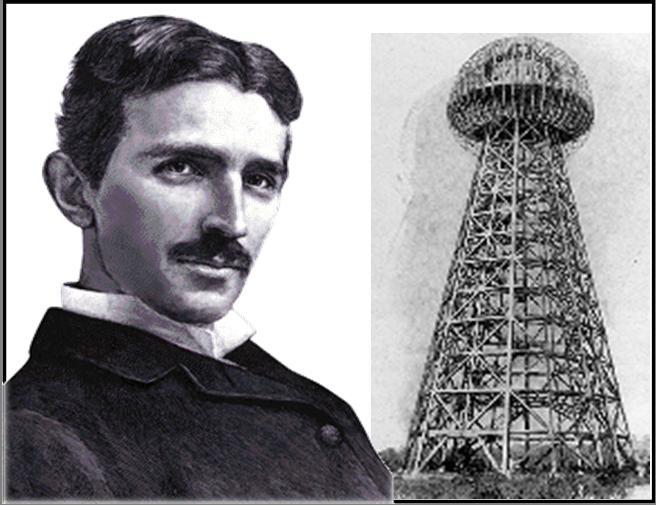
The scientist was born in the family of a Serbian Orthodox priest in the territory of present-day Croatia. At six years old, the boy discovered a wonderful phenomenon when he was playing with a black cat: her back suddenly lit up with a strip of blue, which was accompanied by sparks when touched. So the boy first learned what "electricity" is. This determined his whole future life.
Scientists own inventions and scientific works on:
Many associate the event, which was named with the name of Nikola Tesla, believing that the huge explosion in Siberia was caused not by the fall of the cosmic body, but by the experiment conducted by the scientist.
At one time in scientific circles there was an opinion that electricity does not exist in nature. But this version was refuted when Franklin established the electrical nature of lightning.
It is thanks to her that amino acids began to be synthesized, which means that life appeared. It has been established that movements, respiration and other processes occurring in the body arise from a nerve impulse, which has an electrical nature.
Everyone knows fish - electric stingrays - and some other species are protected in this way, on the one hand, and hit the victim, on the other.
Electricity is connected through the operation of generators. Power plants generate energy transmitted through special lines. Current is generated by converting internal or electric. The stations that produce it, where the connection or disconnection of electricity occurs, are of various types. Among them are:
Electricity is connected almost everywhere today. Modern man cannot imagine life without him. With the help of electricity, lighting is provided, information is transmitted by telephone, radio, television ... Due to it, such vehicles as trams, trolleybuses, electric trains, subway trains operate. Electric cars appear and boldly declare themselves.
If there is a power outage in the house, then a person often becomes helpless in various matters, since even household appliances work with this energy.
The properties of the phenomenon have been studied since ancient times. Mankind has learned how to conduct electricity using various sources. This greatly facilitated their life. Nevertheless, in the future, people still have a lot of discoveries related to electricity.
Some of them, maybe even already been made famous by Nikola Tesla, but then were classified or destroyed by him. Biographers claim that at the end of his life, the scientist burned most of the records with his own hands, realizing that humanity is not ready for them and can harm itself, using its discoveries as the most powerful weapon.
But according to another version, it is believed that some of the records were seized by US intelligence. The history of the US Navy destroyer Eldridge is known, which not only had the ability to be invisible to radar, but also moved instantly in space. There is evidence of an experiment after which part of the crew then died, the other part disappeared, and the survivors went crazy.
One way or another, it is clear that all the secrets of electricity have not yet been revealed. Therefore, humanity is morally not yet ready for this.
In this article we will try to figure out what electricity is and find out the history of its discovery.
Matter has a special property - electric charge. It can be of two types - positive and negative - and it must be said that unlike electric charges are attracted with extraordinary force, as it happens inside atoms. The proton is the carrier of the elementary positive charge, the electron is the negative charge. An electric charge causes physical phenomena, mainly related to the interaction and energy of electrons and manifested in a variety of forms - thermal, mechanical, light, as well as chemical.
Usually when we talk about electricity, we mean the property of matter. But the concept of “electricity” has two more definitions: a form of energy based on this property, and a section of physics that studies electrical phenomena. In any of its three meanings, the word "electricity" plays a fundamental role for human society. The modern world would not have been possible without it. Nevertheless, mankind did without electricity until the beginning of the 20th century.
Although the phenomena associated with electricity can be observed in nature, people have come a long way to fully understand this property of matter and the possibility of control over it, which has significantly improved the standard of living. The Greeks have already observed how one of the types of fossil resin acquires the property of attracting feathers, threads and fluff when rubbing it with a piece of skin. We know this kind of resin today as amber; the Greeks called it an electron. In the Elizabethan era, the Englishman William Hilbert (1544-1603), a researcher of magnetism, discovered that friction also gives this property to other materials. It was thanks to him that the words “electricity” and “electric” were fixed in the language from the Greek “electron”.
In 1733, the French chemist Charles Dufe (1698-1739) discovered that two rods of the same material - amber or glass - mutually repel each other when rubbed. At the same time, rods of different materials are attracted (see Figure 1).
The poles of a magnet behave in a similar manner. If the rods are in contact, the interaction ceases. Therefore, it seemed that there were two different types of “electricity”.
The North American politician, scientist and inventor Benjamin Franklin (1706-1790) also wanted to know what electricity is and was the first to talk about the presence of a positive and negative charge. When he rubbed the glass rod, “electricity” flowed inside the rod, “positively charging it”, and during friction of amber, “electricity” came out of it, “charging negatively”. The contact of the rods with opposite charges forced the positive charge to flow into a negative charge until equilibrium was reached. In 1785, Charles Coulomb measured the ratio and magnitude of the attraction and repulsion of charges. Coulomb's law states that force is inversely proportional to the square of the distance separating the charges and proportional to the magnitude of the charges.
What happened inside the rods that carefully held so many famous scientists in their hands? To understand this, it was necessary to study matter, the structure of the atom is so
deeply as we studied them today. In a somewhat simplified form, we can say that the nucleus, which includes protons and neutrons. The main part of the mass of the atom is concentrated in the nucleus; the other part of the mass is represented by electrons orbiting around the nucleus. The structure of an atom is stable to a large extent due to electromagnetic force. The total charge of protons is positive, for neutrons, as their name implies, is neutral, for electrons is negative. An atom in its unity is neutral. Moreover, in some materials, electrons have a sufficient degree of independence from nuclei and can move relative to them. The movement (flow) of electrons is called an electric current. Most of the practical applications of electricity are related to the flow of electrons, which was observed but not noticed by the first researchers.
After discovering the basic aspects of electricity, scientists had to make a lot of efforts to explore the phenomenon more deeply. Eighteenth-century experimenters noticed that electricity flows freely through some bodies, such as metals (today we call them “conductors”), and cannot easily pass through others, such as glass or amber, which today are known as “insulators”. The idea arose of using this property in order to “catch” and possibly store electricity. To achieve these goals, it was necessary to gradually accumulate a large electric charge in the conductor, then isolate it with glass or a layer of air to prevent loss of electricity.
The device that met all of the above requirements and is known today as a capacitor was the Leyden jar, which was simultaneously and independently created in 1745 by the German professor Georg von Kleist (1700-1748) and the Dutch physicist Peter van Mushenbruck (1692-1761). The vessel - a glass jar - was charged using a metal rod passing through the cork; charge accumulated in the glass. The Briton William Watson (1715-1787) added one more detail to this design in 1747: he proposed to glue the tin with sheets of tin, which increased the charge (see Figure 2).
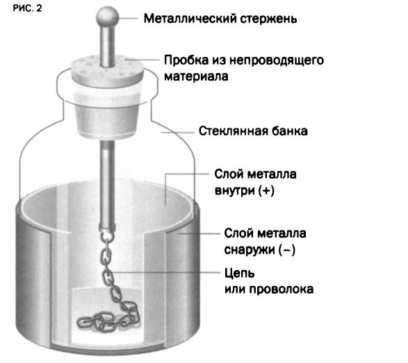
Thanks to the strong charge of the can, admiring spectators could watch the whole performance with sparks and bangs, and when it came into contact with the can, a discharge arose. So what happened inside?
Leiden Bank explains the main electrical phenomena. Electrons naturally tend to move from a zone with a high charge density to zones with a lower density. A force that entails electrons, or, in other words, gives an impulse to the movement of charges, is called an “electromotive force” (EMF), or, from a position of energy, “electric potential”. If the electric potential increases sufficiently, the electrons will occupy the space separating the negative and positive poles. Then they will pass through the air, emitting sparks and making a crackle. Sparks arise from the collision of electrons with air molecules; the sound comes from the expansion of air during sudden heating. The potential difference between two points of the conductor is determined using a physical quantity called electrical voltage; voltage measuring device - voltmeter.
In the 18th century, marveling at the sparks and cod produced by the Leyden jar, many scientists had to wonder if thunder and lightning were phenomena of the same type. It was definitely this question that led Benjamin Franklin to the famous experiment with a kite, which is better not to try, because, according to the scientist himself, the most successful result was that he managed to survive.
Ether of the Universe
Chapter 1. Without a microscope - deep into the microworld
§ 5. The ethereal nature of electric charges, fields, currents, electron emission and magnetism
<...> Final provisions.. Offering to return the ether medium and ether as a building material of significant matter (substance) into scientific circulation, we proposed our own interpretation of the concepts of electric charges, fields, currents, electron emission and magnetism.
Currently, electric charges are divided into positive and negative. The source of a negative electric charge is considered to be an electron and ions of atoms and molecules, which have attached additional electrons; a negative charge is indicated by a minus sign (-). The source of a positive electric charge is considered to be protons and ions of atoms and molecules that have lost some of their electrons; a positive charge is indicated by a plus sign (+).
An electric charge is a localized portion of the surface of a charged body and the perturbed ether space above it, which is disturbed by the rotation of a source on a charged surface - an electron or proton. The charges have an equal magnitude (module) and the same directions of the electric fields created by them. The physical essence of electrically charged bodies is reduced to an excess or lack of ether on their surfaces. Neither positive nor negative charges move in the conductor. The charges are not reduced to their sources and cannot be identified with them when they move, when we talk about electric current.
In order to bring the names of electric charges and their designations in line with real physical processes, it is proposed to change the names and designations of the signs of electric charges to inverse, that is, the opposite of those currently accepted.
An electron as a source of electric charge is a ring-shaped ether structure formed from the ether shell of a proton, which is a source of excess ether. An electron should be considered a positively charged particle with a plus sign (+). The body on whose surface electrons are formed (excess ether) should be considered a positively charged body. An electric field formed by a combination of positive charges should be considered a positive electrostatic field. Atoms or molecules that have acquired electrons should be considered positively charged ions with a plus sign (+).
A proton as a source of electric charge is a proton that has lost its ether shell and is deficient in ether, and should be considered a negatively charged particle with a minus sign (-). The body, on the surface of which bare protons formed (ether deficiency), should be considered a negatively charged body. The electric field formed by a set of negative charges should be considered a negative electrostatic field. Atoms or molecules that have lost their ether shells should be considered negatively charged ions with a minus sign (-).
The proposed new name and designation of electric charges corresponds to the direction of the lines of electric field strength and the direction of the flow of electric current, accepted in earlier times and preserved up to now - from plus (+) to minus (-).
A single positive electric charge is an ether shell separated from the proton of the mother’s body and transferred to the surface of another body or to another part of its surface as a result of external influence. The severed ether shell twists almost instantly into a ring-shaped structure, identified with the electron. This electron forms an ethereal power tube above itself, the tension vector of which is directed perpendicular to the surface of the body. Electrons as positively charged particles are able to move along the surface of the body and transfer to other bodies. The set of single positive electric charges forms a positive electrostatic field and makes the body positively charged.
A single negative electric charge is a proton that has lost its etheric shell as a result of external influences. The bare proton forms an etheric power tube above itself, the tension vector of which is directed perpendicular to the surface of the body. Protons as negatively charged particles on the surface of the body do not move and do not come off the mother’s body. The set of single negative electric charges forms a negative electrostatic field and makes the body negatively charged.
Positive charges (excess ether, electrons) disappear, dissolve, turning into an ether stream when in contact with a body that is deficient in ether, or in contact with the ground. An insulated conductor can be charged positively with excess ether from contact with a positively charged body or charged negatively with ether deficiency from contact with a negatively charged body. Negative charges (ether deficiency, bare protons that have lost the ether shells surrounding them) disappear, replenishing the ether from the ether stream when it comes in contact with a positively charged body.
The Earth as a body with a giant electrical capacity is never, under any circumstances, a source of positive (according to the proposed new designation of charges) electric charges (electrons), that is, it is impossible to make up the missing ether for a negatively charged body from the earth. However, it is possible to imagine a situation where a more electric-intensive celestial body, in contact with the Earth, can take away part of the ether from the Earth. But in reality this is impossible, because the collision of large celestial bodies leads to their destruction.
Positive and negatively charged surfaces are attracted to each other by twisting the electric power tubes forming the electric fields, like the screw and nut connections.
The positively charged surfaces repel each other due to the collision of the fronts of the ether power tubes (ether-rich fields) propagating to each other. Negatively charged surfaces repel each other due to the retraction of free ether of each of the ether-deficient surfaces.
In a generalized form, an electric field is a section of free space (free ether), brought into excitation (voltage) by a set of electric charges forming an electrically charged surface. The maximum excitation (voltage, intensity) of the electric field falls on the surface of the charged body, the excitation decreases with distance from the surface of the body. The practically measured portion of the excitation (voltage, intensity) of the electric field, depending on the density of charges on a charged surface, reaches tens and hundreds of meters. An electric field of alternating current is formed not by electric charges, but by a stream of surface ether flowing through a conductor.
An electric current is a stream of released ether formed in a current source - in a galvanic cell, alternating current generator or on a positively charged surface when it is closed into an electric circuit. There are no conduction electrons and an electric field in the conductor. The movement of ether in the conductor is provided by the conductive systems of its atoms in the presence of a potential difference on the electrodes in a closed electrical circuit. Such potentials appear due to the different structure and properties of the substance of the electrodes.
The electric current, or ether stream, spiraling along the circumference of the surface of the conductor spiral, partially splashes out through the output ports of the conductive systems of the atoms of the conductor and excites the surrounding ether medium in the form of rotating ethereal tourniquet-like structures surrounding the conductor. The vortex excitation of the free ether that occurs in this case is inaccurately called the magnetic field of the electric current. This field should be called an electrodynamic field, since it does not have any basic signs of magnetism, except for the deviation of the magnetic arrow perpendicular to the general direction of the current in the conductor.
From the ether-mechanical position, the mechanism of the formation of ball lightning, which arises due to the potential difference arising between the ether-rich clouds and the ether-insufficiently charged near-surface layers of warm air over dry sandy or clay parts of the earth's surface, is convincing. Developing in the usual way, streamers rush along the main channel after the leader to the earth’s surface and, reaching warm near-surface ionized layers of air, can’t pass into the earth’s rocks, which in this situation are nothing but an excellent natural insulator. Faced with resistance, the released ether stream, together with the strongly ionized and excited atoms of the air molecules, is twisted into a separate ether-plasma ball.
The unique phenomenon of metal superconductivity is also well explained from the ether-mechanical position. As the temperature decreases to a critical level, the etheric shells of atoms lose their outer layers and decrease to such an extent that they become smooth and strong. The gaps between the conductive elements of atoms and the rotation speed of the conductive elements themselves increase. The ether stream entering the conductor system of the atoms of the conductor is not scattered and does not slow down, as in the usual state, but without losses it is distilled over the surface of the hydrogen-like elements of the conductor system of atoms of the conductor.
For ourselves, we raised the question of the ratio of the superfluidity of liquid helium to the superconductivity of metals, since these phenomena occur at extremely low temperatures. Comparing the physical processes occurring in these phenomena, we came to the conclusion that helium superfluidity is characterized by a dense interaction of helium atoms, while superconductivity, on the contrary, is characterized by an increase in the distance between metal atoms and their current-conducting systems.
The appearance of electric current in semiconductors when they are heated in a closed electrical circuit confirms the ethereal nature.
At the core of the atom of the brightest representative of the class of semiconductors - non-metallic silicon - there is a carbon-like conductive system in which there are two input and two output ports located at an angle of 109 ° 28 \\ "each with respect to each other. The connection of one silicon atom with another atom is twisted an etheric jet connecting one of the output ports of one atom with one of the input ports of the other atom.The presence of four etheric jets (two input and two output) provides a closed nature of the movement of ether fluxes between silicon atoms. Such a combination of atoms provides a low electrical conductivity of silicon. When heated, the influx of ether into closed ether streams in silicon atoms increases, which leads to rupture of some of them. In this case, some input and output ports of silicon atoms open and conductive systems as a result of the contact of the ether shells of two neighboring protons, rotating in opposite directions.
In all types of electron emission, the ether shell is torn off from surface atoms under the influence of external forces or the outflow of a high-speed ether from the cathode surface to the ether space. In both cases, the ether, faced with the resistance of a dense free ether medium, collapses into significant ether rings, called electrons. Only in free space do these etheric rings acquire the property of mass and inertia of motion and become complete elementary particles - electrons.
The long-observed close connection between electrical and magnetic phenomena leads to the conclusion about their single ethereal nature. In electricity, it is represented by charges, electrostatic and electrodynamic fields, electric current, and in a man-made solenoid - by a flow of electromagnetic induction. In magnetism, it is represented by vortex magnetic ether flows of permanent magnets, and in a man-made solenoid, it is also a flux of electromagnetic induction.
Magnetism between conductors with electric current does not have the signs of permanent magnets and cannot be considered as one of the forms of magnetism. Such conductors are not attracted to each other until they touch each other, as is the case when the permanent magnets are mutually attracted by opposite poles or oppositely charged electrically charged bodies, but only come together slightly due to the partially combined ether-dynamic fields of each of the conductors.
The source of the magnetic field is not moving electric charges, that is, electric current in conductors or elementary circular currents in permanent magnets, but poles of a permanent magnet (solenoid), which are emitted into the space or draw streams of high-speed ether from it.
The movement of the vortex, closed around its poles, ether flows and is what is called a magnetic field. That is, the magnetic field is a portion of the free ether space (free ether), set in motion by its source - the corresponding poles of the permanent magnet.
The definition of magnetism as a special form of material interactions arising between moving electrically charged particles cannot be considered reliable, since only electrons, electrons, alpha particles and ionized atoms and molecules in free space are moving electrically charged particles, but their chaotic motion does not generate magnetic fields, and in solids such particles do not move.
On the atomic scale of permanent magnets, microscopic currents are represented by ether currents flowing in the form of jets along piping systems assembled from atoms of a magnet, such as iron, oriented in the same direction.
Magnetism as a physical phenomenon, along with electricity, most clearly confirms the existence of ether. The entire diversity of the investigated properties of magnetic fields and the nature of attraction between bodies refers to the manifestations of a moving ether.
The solenoid, like the permanent strip magnet, has a neutral zone, which is located on its surface and above it throughout the entire (removal) of the magnetic field in the plane and coincides with the section plane of the solenoid in the place of its geometric middle.
Two magnetic fields are formed in the solenoid, one is internal, and the other is external. Inside the solenoid, the magnetic field is uniform, outside the solenoid it is inhomogeneous. In the middle part of the solenoid, the internal magnetic flux flows continuously, and in the near-surface regions it is separated by a neutral zone. The structure of the magnetic field of the solenoid is formed by single circular tow-shaped ether streams surrounding the spiral turns of the conductor of the solenoid winding when an electric current passes through them.
The external magnetic flux related to the south (input) pole of the solenoid is directed in the direction opposite to the direction of the internal magnetic flux due to the splashing of part of the internal ether stream in the form of jets into the free space and its reverse drawing into the inter-turn circular electric ether flows and then to the internal magnetic flux. The external magnetic flux related to the north (output) pole of the solenoid is also directed in the direction opposite to the direction of the internal magnetic flux due to the splashing of part of the internal ether stream in the form of jets into free space. This ether stream partially dissipates in the free ether space, compacting it, and for the most part it is bent by the elastic free ether medium in the opposite direction and through the turns of the solenoid winding it is pulled back into the solenoid, replenishing the internal magnetic flux.
The internal magnetic flux continuously flows inside the solenoid and has two poles, input and output. The incoming ether stream enters the south magnetic pole of the solenoid, and the emerging ether stream exits the north magnetic pole of the solenoid. But this is not the same stream, but two streams separated by the neutral zone of the solenoid. The passage of the magnetic flux inside the solenoid does not exceed the speed of light due to the viscosity and inhibitory properties of the free ether.
A cylindrical-shaped permanent magnetic field arises only outside the magnet’s body around its poles and is divided into two equal parts, separated by a neutral zone that originates from the surface of the magnet and is limited by the field of action of the magnetic fields of the poles. Unlike the magnetic field of the solenoid, there is no internal magnet in the body of the permanent magnet.
When escaping from the north magnetic pole and encountering the resistance of a dense and almost motionless free ether, the ether jets of magnetic power tubes begin to expand, scatter and wrap in the opposite direction, again being drawn into the surface of the magnet near their own north pole. This expanding and dissipating ether stream in free ether constitutes what is called the magnetic field of the north pole of the permanent magnet. At the south pole, a mirror process occurs: scattered, losing speed and turned in the opposite direction ether streams of magnetic power tubes that break out of the surface of the magnet adjacent to its south pole are drawn in by the suction surface of the south magnetic pole. This scattered and retracting ether stream in free ether constitutes what is called the magnetic field of the south pole of the permanent magnet.
If the radius of the permanent cylindrical magnet is equal to half the length of the magnet, then the neutral zone is almost at the junction of the magnetic fields that arise around each of the poles of the magnet. The neutral zone divides the magnetic field of the magnet into two equal parts. In this case, the tension lines of each of the fields formed by the two poles of the magnet have the same vector (direction), but both of these fields themselves are not combined by a common ether magnetic flux. The neutral zone of the permanent magnet is located both on the surface and above the surface, perpendicular to it.
A new idea of \u200b\u200bthe structure of elementary magnets in ferromagnets is proposed in connection with the hypothesis of the structure of iron atoms and other magnets, which consist of rather complex ring-shaped structures of oxygen, fluorine, and chlorine atoms with the participation of isotopes of hydrogen atoms. Connecting between the input and output ports (attracting and repelling surfaces), they form a kind of elementary solenoids whose magnetization lies in the direction of their spatial orientation under the influence of an external magnetic field.
The interaction of permanent magnets is a vivid manifestation of the mechanical properties of ether. If the magnetic field around the conductor with the current is a concentrically swirling bursts of ether bundles, then the ether flows in magnets near their poles and surfaces are a combination of ether streams resembling water jets flowing from a pipe with a nozzle-spray at the end.
When the magnets of the same size are brought together by the side surfaces in a position in which the same poles of these magnets are directed in the same direction, they are repelled from each other as a result of the resistance of the pole and side ether streams, which cannot combine to form a common ether stream. When the magnets of the same size are brought together by the side surfaces in a position in which the same poles of these magnets are directed in different directions, they are attracted to each other as a result of the union of the pole and side ether streams, which form a common ether stream.
When the magnets of the same size are brought together by the same and opposite poles, two types of interactions also occur: attraction and repulsion.
Opposite magnetic poles are attracted to each other by magnetic power tubes due to the addition of the floor
Physics Abstract
What is electricity?
1.1 Thermal (TPP)
1.3 Hydroelectric Power Station
1.5 Wind farm
2. The use of electricity
2.1 Transformer (from lat. Transformo - convert)
2.2 Transformer Components
2.2.1 Terminals
2.2.2 Coolers
2.2.3 Gas relay
2.2.5 Oil protection systems
2.2.10 Flammable gas detector
2.2.11 flow meter
2.3 Auto Transformer
2.5 current transformer
2.5.1 Connection diagrams of current transformers
2.6 voltage transformer
List of references
Introduction
To begin with, electricity has been studied for many thousands of years, but it is still not known exactly what it is! Today it is believed that it consists of tiny charged particles. According to this theory, electricity is a moving stream of electrons or other charged particles. The first scientist who studied the properties of electricity was Queen Elizabeth's court physician 1 William Gilbert . But, despite his interesting discoveries, one cannot say that he or someone else from the scientists really discovered electricity, because from ancient times to the present day many scientists study the properties of electricity, analyze new forms of its application. Therefore, we will only talk about the most important discoveries in this area.
So in Holland in 1745 invented special leiden banks in which a huge charge of those times could accumulate (of the order 1 microcoulomb) English scientist Watson improved this invention, and discovered that the speed of propagation of electricity is huge and it acts, therefore, almost instantly.
Perhaps the science of electricity began to develop rapidly from the moment that in 1800 Alessandro Volta invented the battery. This invention gave people the first permanent and reliable source of energy and entailed all the important discoveries in this area. Dynamo machine Faraday , electromagnetic theory Maxwell , the science Electrodynamics created with filing Ampere - All this happened over some 20 years. And then, in 1871, an American scientist Edison gave the world the first incandescent lamp , and only after 40 years the Frenchman Georges Claude invented neon lamp.
By the way, electricity is not an artificial phenomenon, it also occurs in nature in the form of ... lightning! Which proved Benjamin Franklin in 1752.
Nowadays, almost all industries use electricity. But factories do not work from lightning and cities are illuminated. To convert various types of energy into electrical energy, power plants.
Depending on the energy source, there are:
Thermal power plants (TPPs) using fossil fuels.
Nuclear power plants (NPPs) using nuclear energy.
Hydroelectric power plants (HPPs) using the energy of falling river water.
Other power plants using wind, solar, geothermal and other types of energy.
The main type of power plants in Russia. These plants produce approximately 67% of electricity Of Russia. Thermal power plants use widespread fuel resources, are capable of generating electricity without seasonal fluctuations, and are relatively freely placed. Their location is influenced by fuel and consumer factors: the most powerful power plants are located in the areas of fuel production; Thermal power plants using high-calorie, transportable fuel are consumer-oriented. The construction of thermal power plants is fast and involves less labor and material resources. But they have significant flaws. They use non-renewable resources, possess low efficiency (30-35%), have an extremely negative impact on the environmental situation. TPPs all over the world annually release 200-250 million tons of ash and about 60 million tons of sulfur dioxide into the atmosphere, and also absorb a huge amount of oxygen.
Among TPPs prevail thermal steam turbine (TPES), on which thermal energy is used in the steam generator to produce high-pressure water vapor, which rotates the rotor of a steam turbine connected to the rotor of an electric generator (usually a synchronous generator). Coal (mainly), fuel oil, natural gas, lignite, peat, and shale are used as fuel at such TPPs. Note that in any power plant a cooling system for the spent heat carrier is provided in order to bring the temperature of the heat carrier to the value necessary for the repeated cycle. If there is a settlement near the power plant, this is achieved by using the heat of the spent heat carrier to heat water for heating houses or hot water supply (such TPES are called heat and power plants (CHP)), and if not, then the excess heat from the heat carrier is simply discharged into the atmosphere in cooling towers which are wide conical pipes. Exhaust steam condensers at non-nuclear power plants most often are cooling towers.
TPPs driven by an electric generator from a gas turbine are called gas turbine power plants (GTES). In a GTES combustion chamber, gas or liquid fuel is burned; combustion products with a temperature of 750-900 ° C enter a gas turbine rotating an electric generator. The efficiency of such TPPs is usually 26-28%, and the capacity is up to several hundred MW (!). GTPPs are typically used to cover peak electrical loads. .
TPP with steam and gas turbine installation, consisting of steam turbine and gas turbine units, called combined cycle power plant (PGES), the efficiency of which can reach 42 - 43%. GTPPs and CHPPs can also release heat to external consumers, that is, operate as CHPPs.
A power plant in which atomic (nuclear) energy is converted into electrical energy. The nuclear power generator is a nuclear reactor. The heat that is released in the reactor as a result of a chain reaction of fission of the nuclei of some heavy elements, then, as in conventional thermal power plants (TPPs), is converted into electricity. Unlike fossil fueled thermal power plants, nuclear power plants operate on nuclear fuel (mainly 233U, 235U.239Pu). When dividing 1 g of uranium isotopes or plutonium is released 22 500 kW / h, which is equivalent to the energy contained in 2800 kg of standard fuel (!). It has been established that the global energy resources of nuclear fuel (uranium, plutonium, etc.) significantly exceed the energy resources of natural reserves of fossil fuels (oil, coal, natural gas, etc.). This opens up broad prospects for meeting rapidly growing fuel needs.
Most often 4 types of thermal neutron reactors are used at nuclear power plants:
1) water - with ordinary water as a moderator and coolant
2) graphite-water - with water coolant and graphite moderator
3) heavy water - with water coolant and heavy water as a moderator
4) graphite gas - with gas coolant and graphite moderator.
Depending on the type and state of aggregation of the coolant, one or another thermodynamic cycle of the nuclear power plant is created. The choice of the upper temperature limit of the thermodynamic cycle is determined by the maximum allowable temperature of the shells fuel elements (TVEL), containing nuclear fuel, the permissible temperature of the actual nuclear fuel, as well as the properties of the coolant adopted for this type of reactor. During reactor operation, the concentration of fissile isotopes in nuclear fuel gradually decreases, i.e. TVELs burn out. Therefore, over time, they are replaced with fresh ones. Nuclear fuel is reloaded using remote-controlled mechanisms and devices. Spent fuel elements are transferred to the exposure pool, and then sent for processing. The profitability of a nuclear power plant is determined by its main technical indicators: unit reactor capacity, efficiency, core energy density, nuclear fuel burnup, installed plant capacity utilization per year. With an increase in the capacity of nuclear power plants, specific capital investments in it decrease more sharply than is the case for thermal power plants. This is the main reason for the desire to build large nuclear power plants with a large unit capacity. It is typical for the NPP economy that the share of the fuel component in the cost of production electricity 30-40% (at thermal power plants 60-70%).
Due to an accident in Chernobyl in 1986 the year, the nuclear energy development program was reduced. After a significant increase in electricity production in the 80s, the growth rate slowed down, and in 1992-1993. recession began. With proper operation, nuclear power plants are the most environmentally friendly source of energy. Their functioning does not lead to the appearance of a greenhouse effect, emissions into the atmosphere during trouble-free operation, and they do not absorb oxygen.
The disadvantages of nuclear power plants include the difficulties associated with the disposal of nuclear waste, the catastrophic consequences of accidents and thermal pollution of water bodies used.
Highly efficient energy sources. They use renewable resources - the mechanical energy of falling water. The necessary water backwater is created by dams that are erected on rivers and canals. Hydraulic units can reduce transportation and save mineral fuel (approximately 0.4 tons of coal is consumed per 1 kWh). They are quite simple to manage and have a very high efficiency ( more than 80%). The cost of this type of installations is 5-6 times lower than TPPs, and they require much less maintenance personnel.
A hydropower plant consists of a series of hydraulic structures that provide the necessary concentration of water flow and pressure generation, and power equipment that converts the energy of water moving under pressure into mechanical rotation energy, which, in turn, is converted into electrical energy. The pressure of the hydroelectric power station is created by the concentration of the fall of the river in the area used by the dam, or by derivation (water drainage from the river channel along the channel), or by a dam and derivation together.
By installed capacity ( in MW) distinguish hes powerful (over 250), medium (up to 25) and small (up to 5). The power of a hydroelectric power station depends on the pressure of water, its flow rate m3 / s), used in hydraulic turbines, and hydraulic unit efficiency. For a number of reasons (due, for example, to seasonal changes in the water level in reservoirs, inconsistencies in the load on the power system, repair of hydraulic units or hydraulic structures, etc.), the pressure and flow rate are constantly changing, and in addition, the flow rate is changing when regulating the power of a hydroelectric power station. Therefore, distinguish between annual, weekly and daily cycles of the mode of operation of hydroelectric power stations.
According to the scheme of water resources use and pressure concentration, hydropower plants are usually divided into channel , dam , derivational with pressure and non-pressure derivation , mixed , accumulators and tidal . In riverbed and dam hydropower plants, water pressure is created by a dam blocking the river and raising the water level in the upper pool. In this case, some flooding of the river valley is inevitable. In the case of the construction of two dams on the same section of the river, the area of \u200b\u200bflooding decreases. On lowland rivers, the largest economically permissible flooding area limits the height of the dam. River and dam hydropower plants are built on both plains, high-water rivers and mountain rivers, in narrow, compressed valleys.
The most powerful hydropower plants were built at Volga, Kama, Hangar, Yenisei, Ob and Irtysh . The cascade of hydroelectric power plants is a group of hydroelectric power plants located in steps along the stream of a water stream in order to make full use of its energy. Installations in the cascade are usually connected by the commonality of the regime in which the reservoirs of the upper stages regulate the reservoirs of the lower stages. On the basis of hydropower plants in the eastern regions, industrial complexes specializing in energy-intensive industries are being formed.
In Siberia, the most efficient technical and economic indicators are concentrated. One example of this is Angara-Yenisei cascade , which includes the largest hydropower plants in the country: Sayano-Shushenskaya (6.4 million kW), Krasnoyarsk (6 million kW), Bratskaya (4.6 million kW), Ust-Ilim (4.3 million kW). Under construction Boguchanovskaya hydroelectric station (4 million kW). The total power of the cascade is currently more than 20 million kW.
A power plant that converts tidal energy into electrical energy. PES uses the difference in levels of "full" and "low" water during high and low tides. Having blocked the bay with the dam or the mouth of the river flowing into the sea (ocean) (having formed a body of water, called the PES basin), at a sufficiently high tidal amplitude (more than 4 m), a head can be created that is sufficient to rotate the hydraulic turbines and the hydrogenerators connected to them located in the body of the dam.
With one pool and the correct semidiurnal tidal cycle, PES can generate electricity continuously for 4-5 hours with interruptions, respectively, 2-1 hours four times a day (such a PES is called single-basin double-acting) To eliminate the uneven generation of electricity, the PES pool can be divided by a dam into two or three smaller pools, in one of which the level of "low" and the "full" water are maintained; the third pool is a reserve; hydraulic units are installed in the body of the separation dam. But this measure does not completely exclude the pulsation of energy due to the cyclical tides over a half-month period. When working together in the same energy system with powerful thermal (including nuclear) power plants, the energy generated by TECs can be used to cover the peak load of the power system, and the hydropower stations included in the same system that have seasonal regulation reservoirs can compensate intramonthly fluctuations tidal energy.
At the PES installed capsule hydraulic units which can be used with relatively high efficiency in the generator (forward and reverse) and pump (forward and reverse) modes, as well as as a culvert. In hours when the light load of the power system coincides with the “small” or “full” water in the sea, the hydroelectric power units are either turned off or operate in the pump mode - they pump water into the pool above the tide level (or pump out below the low tide level) and T. about. accumulate energy until the moment when the energy system comes peak load . In the event that the tide or ebb coincides in time with the maximum load of the power system, the PES works in generator mode.
The use of tidal energy is mainly limited by the high cost of constructing TEC ( the cost of constructing a TPP is almost 2.5 times more than an ordinary river hydropower plant of the same capacity) In order to reduce it in the USSR, the so-called surfacing method used in marine hydraulic engineering (tunnels, docks, dams, etc. structures). The essence of the method lies in the fact that the construction and installation of the object is carried out in favorable conditions of the coastal industrial center, and then the assembled object is towed by water to the place of its installation. In this way in 1963-1968 on the coast of the Barents Sea in sour lip (Shalim) The first experimental industrial PES was built in the USSR. Creature PES Rane and Kislogubskaya PES and their pilot operation allowed us to start drafting Mezenskaya TPP (6-14 GW) in the White Sea, Penzhinsky (35 GW) and Tugur (10 GW) in the Sea of \u200b\u200bOkhotsk.
Generates electricity as a result of the conversion of wind energy. The main equipment of the station is a wind turbine and an electric generator. Constructed mainly in areas with a stable wind regime.
Steam turbine power plant using the deep heat of the Earth. In volcanic regions, thermal deep waters are heated to temperatures above 100 ° C at a relatively shallow depth, from where they come to the surface through cracks in the earth's crust. At geothermal power plants, the steam-water mixture is discharged through boreholes and sent to a separator, where the steam is separated from the water; steam enters the turbines, and hot water after chemical treatment is used for heating needs. In Russia, similar power plants were built in Kamchatka: Pauzhetskaya (11 thousand kW).
These days, hydroelectric and nuclear power plants emit the most electricity. But the functioning of thermal, nuclear and hydropower plants negatively affects the environment. Therefore, much attention is currently being paid to studying the possibilities of using non-traditional, alternative energy sources. The practical application has already received the energy of the tides and the internal heat of the Earth. Wind power plants are available in residential villages of the Far North. Work is underway to study the possibility of using biomass as an energy source. In the future, perhaps a huge role will be played by solar energy. Installations that operate on the energy of the Sun (albeit of low power) are built in the USA and France.

Static (non-moving parts) electromagnetic device for conversion by electromagnetic induction AC systems of one voltage to an alternating current system of another voltage at a constant frequency and without significant power loss. The transformer consists of one (autotransformer) or several insulated wire windings covered by a common magnetic flux, wound, as a rule, on a magnetic core (core) of ferromagnetic soft magnetic material.
Terminals in dry transformers can be wired to the terminal block in the form of bolted contacts or connectors with flat contacts. Terminals can be placed inside the housing. In sealed oil or liquid transformers, electrical connections are moved from the inside of the tank to the outside:
Bushing insulators - a terminal block in the form of a bushing transfers the connections from the internal insulating medium of the transformer to the external insulating medium, there are:
Low voltage bushings
Capacitor bushings
High current bushings.
Thermometers are usually installed in the winding to measure the temperature of the oil in the upper layer and to indicate dangerous overheating points. If overheating occurs, the cooling equipment collects the hot oil in the upper part of the tank and returns the cooled oil to the lower side. The refrigeration unit has the form of two oil circuits with indirect interaction, one internal and one external circuit. The internal circuit transfers energy from heating surfaces to oil. In the external circuit, the oil transfers heat to the secondary cooling medium. Transformers are usually cooled by atmospheric air.
Types of coolers:
Radiators - there are different types. Basically, they are many flat channels in the plates with an end weld, which connect the upper and lower collectors.
Corrugated tank - It is also a tank and cooling surface for distribution transformers of small and medium power. Such a tank has a lid, corrugated tank walls and a lower box.
Fans For large assemblies, it is possible to use suspended fans below or on the side of the radiators to provide forced air movement and natural oil and forced air (ONAF) cooling. This can increase the load capacity of transformers by about 25%.
Heat exchangers with forced circulation of oil, air. In large transformers, heat removal through natural circulation through radiators requires a lot of space. Space requirements for compact coolers are much lower than for simple radiator batteries. From the point of view of space saving, it may be advantageous to use compact coolers with significant aerodynamic drag, which requires the use of forced circulation of oil using a pump and powerful fans for pumping air.
Oil-water coolers As a rule, they are cylindrical tubular heat exchangers with removable tubes. Such heat exchangers are very common and represent a classic technology. They have diverse applications in industry. More modern designs, for example, flat membrane-type heat exchangers, have not yet entered into practice.
Oil pumps. Circulating pumps for oil cooling equipment are special compact, completely sealed structures. The engine is immersed in transformer oil; stuffing boxes are missing.
A gas relay is usually located in the connecting pipe between the tank and the expansion tank. The gas relay performs two functions: the sensor function, when the oil flow between the tank and the expansion tank exceeds a predetermined value, and also accumulates free gas bubbles that move towards the expansion tank from the transformer tank
Current transformers can be located inside the transformer, often near a grounded sleeve on the oil side of the bushings, as well as on low voltage buses. In this matter, price, compactness and safety play a role. With this solution, there is no need to have several separate current transformers at the sorting station with external and internal insulation, designed for high voltage.
The most common oil protection system is an open expansion tank in which air above the oil level is vented through a desiccant device. It is necessary to remove moisture from the air space above the oil level in the expansion tank to ensure that there is no water in the transformer oil.
The expansion tank of the transformer can be equipped with an inflatable pillow. A synthetic rubber inflatable pillow is placed above the oil. The interior of the cushion is connected to the atmosphere, so it can inhale air when the transformer is cooled and the volume of oil is compressed, and exhale air when the transformer heats up.
Another solution is an expansion tank, which is horizontally separated by a membrane or diaphragm, which allows the oil to expand or contract without direct contact with outside air. The space above the oil in the expansion tank can be filled with nitrogen from a compressed gas cylinder through a pressure reducing valve. When the transformer inhales, the pressure reducer releases nitrogen from the cylinder. When the volume increases, nitrogen enters the atmosphere through the vent valve. In order to save nitrogen consumption, you can set a certain pressure step between filling with nitrogen and the release of nitrogen.
Transformers can have hermetic execution. In small oil-filled distribution transformers, an elastic corrugated tank can compensate for oil expansion. Otherwise, it is necessary to provide a space above the oil inside the transformer tank filled with dry air or nitrogen, so that they act as a cushion when expanding or compressing the oil. You can use a combination of different solutions. The transformer tank can be completely filled with oil, and at the same time have a large expansion tank of sufficient volume to expand the oil and the necessary gas cushion. This gas cushion may be continued in the next additional tank, possibly at ground level. To limit the volume of the gas cushion, you can open a message with the outside atmosphere at the specified upper and lower limits of internal pressure.
An arc discharge or short circuit that occurs in an oil-filled transformer is usually accompanied by the occurrence of overpressure in the tank due to gas generated during decomposition and evaporation of the oil. The pressure relief device is designed to reduce overpressure due to internal short circuit and thus reduce the risk of tank rupture and uncontrolled oil leakage, which can also be complicated by fire due to short circuit. The low weight of the valve disc and the low spring stiffness of the closing springs ensure quick and wide opening. The valve returns to its normal closed state when overpressure is released.
The relay for sudden pressure increase is designed to operate when an elastic oil wave occurs in the transformer tank in case of serious short circuits. This device is able to distinguish between fast and slow pressure buildup and automatically trips the switch if the pressure rises faster than specified.
Power transformer protection devices are. Elements of relay protection and automation equipment, on transformers 6 / 10kV fuses are more often used.
Large units in practice are rarely delivered by crane to their installation site on the foundation. They need to be moved in some way from the vehicle to the base. If cast rails are laid from the place of unloading from the vehicle to the place of final assembly of the unit, then the unit can be equipped with rolling wheels. Rotation of 90 degrees for transport purposes is provided by wheels working in two directions. The unit is lifted by a lift and the wheels are turned. When the unit is installed in place, the locked wheels can be on it or removed and replaced with support blocks. You can also lower the unit directly onto the foundation. If such a rail system is not provided, then ordinary flat guides are used. The unit is pushed along greased rails directly to the installation site, or a track chain is used. The unit can be welded to the foundation on which it is installed. The unit can also be placed on a vibration base to reduce noise transmission through the foundation.
A combustible gas detector indicates the presence of hydrogen in the oil. Hydrogen is trapped through the dialysis membrane. This system gives an early indication of a slow gas generation process before free gas begins to sparge in the direction of the gas storage relay.
To control the flow of oil from the pumps, oil flow meters are installed in transformers with forced cooling. The operation of a flowmeter is usually based on measuring the pressure difference on either side of an obstacle in the oil flow. Flow meters are also used to measure water flow in water-cooled transformers. Typically, flow meters are equipped with alarms. They may also have a dial indicator.
So, we examined the components of the transformer. We pass to the species.
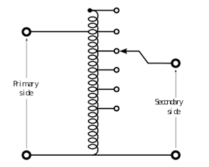
A variant of a transformer in which the primary and secondary windings are connected directly, and due to this, they have not only electromagnetic coupling, but also electrical coupling. The autotransformer winding has several leads (at least 3), connecting to which, you can get different voltages. The advantage of the autotransformer is a higher efficiency, since only part of the power is converted, this is especially important when the input and output voltages differ slightly. The disadvantage is the lack of electrical isolation (galvanic isolation) between the primary and secondary circuit. In industrial networks, where the presence of grounding of the neutral wire is necessary, this factor does not play a role. But significant is the lower consumption of steel for the core, copper for windings, less weight and dimensions, and as a result - lower cost. Laboratory Autotransformer Adjustable (LATR), unlike a simple autotransformer, it has a movable current collector contact to the winding, which allows you to smoothly change the number of turns included in the secondary circuit, and, therefore, the output voltage, from almost zero to the maximum value for this LATR model. LATRs are used to power laboratory facilities, to stabilize the voltage in the mains and other needs.
2.4 Power Transformer
A stationary device with two or more windings, which by means of electromagnetic induction converts an alternating voltage and current system into another system of voltage and current, as a rule, of different values \u200b\u200bat the same frequency in order to transmit electricity.

A transformer designed to measure high currents. The primary winding of the current transformer is included in the circuit with the measured alternating current, and measuring instruments are included in the secondary. The current flowing through the secondary winding of the current transformer is proportional to the current flowing in its primary winding. Current transformers are widely used for measuring electric current and in devices for relay protection of electric power systems, in connection with which high requirements for accuracy are imposed on them. Current transformers ensure the safety of measurements by isolating the measuring circuits from the primary circuit with a high voltage, often of hundreds of kilovolts.
High accuracy requirements apply to current transformers. As a rule, a current transformer is performed with two groups of windings: one is used to connect protection devices, the other, more accurate - to connect metering and measurement tools (for example, electric meters). The secondary windings of the current transformer must be closed (through the load or directly) and grounded. A high voltage appears on the secondary winding, sufficient for breakdown of the transformer insulation, which leads to the failure of the transformer, and also poses a threat to the life of maintenance personnel. In addition, due to increasing losses in the core, the transformer magnetic core begins to overheat, which can also lead to damage (or at least to wear) of the insulation and its further breakdown. For these reasons, during operation of the current transformer, its secondary winding cannot be kept open.
A transformer designed to convert high voltage to low in measurement circuits. The use of a voltage transformer isolates the protection and measurement circuits from the high voltage circuit.
Earthed - a single-phase voltage transformer, one end of the primary winding of which must be tightly grounded, or a three-phase voltage transformer, the neutral of the primary winding of which must be tightly grounded.
Non-earthed - a voltage transformer in which all parts of the primary winding, including the terminals, are isolated from earth to a level corresponding to the voltage class.
Cascade - a voltage transformer, the primary winding of which is divided into several series-connected sections, the transmission of power from which to the secondary windings is carried out using tie and equalizing windings.
Capacitive - voltage transformer containing a capacitive divider.
Double winding - voltage transformer having one secondary voltage winding
Three-winding - voltage transformer having two secondary windings: primary and secondary.
1. Fundamentals of the theory of chains, G.I. Atabekov, Doe, St. Petersburg., - M., - Krasnodar, 2006.
2. Electric machines, L.М. Piotrovsky, L., "Energy", 1972.
3. Kislitsyn A.L. Transformers: A manual on the course "Electromechanics". - Ulyanovsk: UlSTU, 2001 .-- 76 p.
4. Power transformers. Reference book / Ed. S.D. Lizunova, A.K. Lohanina. M .: Energoizdat 2004 .-- 616 p.
5. Electric machines: Transformers: A manual for electromech. specialist. universities / B.N. Sergeenkov, V.M. Kiselev, N.A. Akimova; Ed. I.P. Kopylova. - M .: Higher. school, 1989 - 352 s.
6. Electric machines, A.I. Voldek, L., "Energy", 1974.
7. Electromagnetic calculations of transformers and reactors. - M .: Energy, 1981 - 392 p.
8. Construction of transformers. A.V. Shoemakers. M .: Gosenergoizdat. 1959.
9. Calculation of transformers. Textbook for universities. P.M. Tikhomirov. M .: Energy, 1976 .-- 544 p.
10. Shabad M.A. "Current transformers in relay protection circuits" Training Edition. 1998 year
11. Rodshtein L.A. "Electrical Appliances: A Textbook for Technical Schools" - 3rd ed., L .: Energoizdat. Leningrad Department, 1981.
12. GOST 18685-73 Current and voltage transformers. Terms and Definitions.
13. GOST 1983-2001 Voltage transformers. General specifications.
From internal pipelines, drains are transported by external ...
Each apartment, like every family, has its own characteristics, so it is difficult ...