From internal pipelines, drains are transported by external ...
The formation of conductive closed circuits around the main magnetic flux or part thereof causes local heating, and in some cases sparking.
In case of violation of the inter-sheet insulation of the plates of the magnetic circuit, as well as when these plates are closed with conductive particles or objects, a short-circuited circuit for eddy currents appears in the magnetic circuit. These currents cause local heating of the magnetic circuit, which accelerates the further destruction of the insulation of the plates. The development of the process may lead to “ fire in steel ” and damage to the transformer (Fig. 6.1).
Fig. 6.1. ”Fire in steel” magnetic circuit
In case of violation of the insulation of the metal fastening elements of the active part of the transformer and (or) improper grounding of the elements of the transformer, a closed conductive circuit arises around the main magnetic flux. In this case, in places of loose contact between the elements of this circuit, local heating and sparking may occur.
The short circuit between the turns of the windings, if it is short, causes an intense release of thermal energy and a quick response of the protection of the transformer acting on its disconnection. When bridging wires in multi-parallel windings, as well as when closing between turns of windings through an increased transition resistance, local heating of the windings is observed, which over time leads to destruction of the insulation and ultimately to a short winding.
All of the above defects associated with the formation of conductive closed loops around the main magnetic flux or part thereof cause an increase in the loss of XX.
In a three-phase transformer, when measuring the loss of XX, three experiments are carried out with the three-phase transformer reduced to a single-phase one by short-circuiting one of its phases and exciting the other two. Shorting one of its phases (or, equivalently, shorting one of its windings) is done in order not to have a magnetic flux in this phase, and therefore not to have any losses in it.
For example, if you short-circuit the phase c and apply voltage to the phases a and blV windings, then the measured losses will characterize the energy loss due to phase excitation a and b (fig. 6.2). We denote these losses, taking into account the closable phase, as P C. In the absence of defects in the transformer, the losses P A and P C, measured by sequentially short-circuiting the extreme phases a and c, will be almost the same (the difference is no more than 2 - 3%), and the losses Р В, measured with the closure of the middle phase bwill exceed the loss of P A or P C by 35 - 40% [L.1]. This is explained by the different length of the magnetic flux closure path when the transformer is excited according to the indicated measurement schemes. Knowing the losses in different phases, you can compare them and make sure that the transformer has the correct loss ratio and has no defects.
If any short-circuited loop occurs around the main magnetic flux of one of the magnetic core rods, the loss ratio measured according to these schemes will change, and the appearance of a short-circuited loop causes an increase in losses, so the defective phase will be the one upon shortening of which the smallest losses are measured. This pattern is used to detect the defective phase [L.2].
The above defects may occur during installation or overhaul transformer. Therefore, in normative documents [L.3] it is proposed to measure the loss of XX during acceptance tests and after major repairs.
At commissioning and overhaul of three-phase transformers, the loss ratio at different phases should not differ from the ratios given in the factory test report (passport) by more than 5%.
When commissioning single-phase transformers, the difference between the measured loss values \u200b\u200bfrom the original ones should not exceed 10%.
Fig. 6. 2. Measurement of loss XX during low excitation with sequential shorting of phases
Measurements during operation are carried out during complex tests of the transformer. The difference between the measured values \u200b\u200bfrom the source data should not exceed 30%.
Assumptions about the defect are rejected if the following conditions are met [L.2]:
Before testing, the transformer must be properly grounded.
Short circuit of one phase can be made on any winding of the transformer, i.e. on the winding, to which voltage is applied during the experiment XX, or another, open winding (Fig. 6.2); they are guided by the actual connection diagram of the transformer windings.
When measuring, voltage is usually applied to two phases of the LV winding, and the third is short-circuited, thereby achieving greater excitation of the magnetic system. The idle test is usually performed on the side of the LV winding, since the measurement of voltage, current and power is easier to perform at a lower voltage.
Before measurements at low voltage, GOST 3484-77 provides for the need to remove the residual magnetization of the magnetic system of the transformer if before these measurements work was carried out related to the flow of direct or alternating current windings, as well as if the transformer excitation is significant (2 times or more) when disconnected exceeded the voltage at which measurements are made. Methods for removing residual magnetization are established by GOST 3484-77.
If possible, a 0.2 voltmeter and wattmeter should be used for measurements.
During the test, the input voltage and the total power consumed by the transformer under test and measuring instruments are measured. Then determine the power consumed by the measuring devices (P CR), by measurement or calculation. The loss measurement in the devices is carried out according to the same scheme as when measuring the total loss (P meas), but with the transformer turned off (Fig. 6.3), with the same voltmeter reading (V).
Fig. 6. 3. The scheme for measuring losses in devices
The consumption of devices can also be determined by the formula
![]() ,
,
Losses in the tested transformer are calculated by the formula:
The losses brought to the rated voltage are determined by the formulas:
In the case of connecting the excited winding into a triangle
In the case of connecting the excited winding into a star
Usually n has the following approximate values \u200b\u200bwhen a transformer is excited with a voltage of 5-10% of nominal:
The value of n can be determined by the formula [L4]
If the input voltage is less than 5% of the nominal, then to reduce the losses, the exponent n should be determined by this formula.
In phase-by-phase measurement, each phase takes part in measurements twice, therefore, the total transformer losses will be:
![]()
The magnetic core of the transformer is made of hot rolled steel with a sheet thickness of 0.35 mm. The measurements were made in phases.
The results are given in table. 7.1.
Table 7.1
| Phase voltage applied | Closed phase | Voltage | Current, A | Losses, watts | Reduced losses, kW |
| a - b | c | 525 | 3,5 | 428 | 89,64 |
| b - c | a | 525 | 3,5 | 428 | 89,64 |
| a - c | b | 525 | 4,8 | 574 | 121,7 |
Voltage (525 V) is 5% of the nominal.
Losses in devices amounted to 20 watts.
Losses reduced to the rated voltage of the LV winding:
P priv. C \u003d P priv. A \u003d (428 - 20) (10500/525) 1.8 \u003d 89.64 kW
P pref. B \u003d (554 - 20) (10500/525) 1.8 \u003d 121.7 kW
P 0 extra \u003d (P extra C + P extra B + P extra A) / 2 \u003d (89.64 + 89.64 + 121.7) / 2 \u003d 150.5 kW,
which is 0.5% more than factory idle losses.
Loss P priv. C and P priv. A are equal, and P pref. B more losses P priv. C and P priv. A:
![]()
All this indicates that the transformer is in good condition and has no defects.
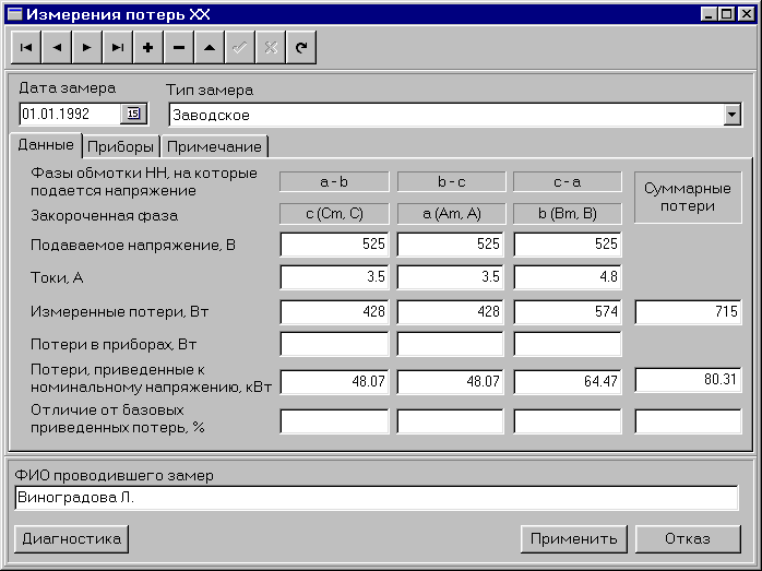
Be sure to enter the "Date of test" and indicate "Type of test."
The form has three tabs: "P aboutteri "," P ribor "and" Pr andsweeping ". You can go to the desired tab by pointing it with the mouse.
In the first tab, the user enters "Voltages", "Currents" and "Measured Losses" for each of the three experiments. For single-phase transformers, only the first column of the table is populated. If the power consumed by the devices was measured during the experiments, then its values \u200b\u200bare also entered in the form fields, and if their resistance is known from the instrument passports, then the losses in the devices will be calculated during the examination and the results will be recorded in the form fields.
The examination also calculates "Losses reduced to nominal voltage" and "Differences in reduced losses from baseline values" for each experiment. In addition, "Total idle losses in all phases of the transformer at a given voltage", "Total idle losses in all phases of the transformer are reduced to the rated voltage" and "Difference in the total reduced idle losses from the basic idle losses at the rated voltage" are calculated.
The basic values \u200b\u200bare the data from the earliest measured idle loss for this transformer.
In the second tab, the numbers of the devices used are entered, and if you need to calculate the losses in the devices, then "Voltmeter resistance" and "Wattmeter voltage winding resistance".
You can enter any text in the notes.
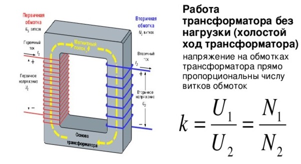
The operation mode of the transformer when feeding one of its windings from an alternating voltage source with other windings open is called idle mode. Losses occurring in a transformer in idle mode at a nominal sinusoidal voltage at the primary winding and at a nominal frequency are called idle losses.
The open circuit losses of the transformer P x are composed of magnetic losses, i.e. losses in the active material (steel of the magnetic system, losses in the steel structural elements of the transformer core caused by partial branching of the main magnetic flux, the main losses in the primary winding caused by the open circuit current, and dielectric insulation losses.
Dielectric loss in insulation can play a noticeable role only in transformers operating at an increased frequency, and in power transformers designed for a frequency of 50 Hz, even with voltage classes of 500 and 750 kV, they are usually small and may not be taken into account. Also, the main losses in the primary winding, usually usually less than 1% of the no-load losses, are not taken into account in power transformers. Losses in the structural elements of the transformer at idle are relatively small and are taken into account together with other additional losses.
Magnetic losses - losses in the active steel of the magnetic system - comprise the bulk of the no-load losses and can be divided into losses from hysteresis and eddy currents. For modern cold-rolled electrical steel with a thickness of 0.35 and 0.30 mm, the first of them account for up to 25-35 and the second up to 75-65% of the total loss.
In practice, at a frequency of 50 Hz, magnetic losses are usually determined without separating them, and the experimentally established relationship between induction and specific losses in steel is used. Since at a given frequency and uniform distribution of induction, losses in a unit mass of steel are uniquely determined by induction, this dependence is expressed in the form of losses in a unit mass of steel p, W / kg, for a given induction. The data of the experimental study of steel are tabulated or plotted as the specific loss curve p \u003d f (B). Specific as well as total losses in steel change with a change in induction B and frequency f. If you need to conduct approximate recalculations of losses with a change in frequency or induction, you can use the approximate formula
where for cold rolled steel n \u003d l, 25; m \u003d 2 at B \u003d 1.0 ÷ 1.5 T and m \u003d 3 at B \u003d 1.5 ÷ 1.8 T. For hot rolled steel n \u003d l, 3; m \u003d 2 at B \u003d 1.0 ÷ 1.5 T.
It should be remembered that the quality of electrical steel of various origins may be different. Therefore, when calculating, you should always use tables or curves relating to the actually used steel.
The specific losses in cold rolled steel grades 3404, 3405, M6X and M4X are given in table 8.10. When using steel grade 3406 with a thickness of 0.27 mm, you can use the data for steel grade M4X with a thickness of 0.28 mm in this table, as well as table. 8.11, 8.13 and 8.14.
Magnetic induction in the rods and yokes of a flat blended magnetic system is determined for the calculated voltage of the winding coil and finally set values \u200b\u200bof the active cross sections of the rod P s and yoke P i,
The open circuit losses of a transformer, the flat laden magnetic system of which is assembled from plates, are determined by its design, the mass of steel of individual sections of the system, the induction in each of these sections, the quality of steel, the thickness of the plates and the technology for the manufacture and processing of plates.
Idling losses in a magnetic system assembled from hot rolled steel plates,
![]() (8.30)
(8.30)
where p c and p i are the specific losses in 1 kg of steel of the rod and yoke, depending on the inductions B c and B i, grades and thicknesses of steel sheets given for steel grades 1512 and 1513 according to GOST 21427-83 in table. 8.9; k d - coefficient taking into account additional losses arising from the uneven distribution of the induction of mechanical stresses on steel during the preparation of plates and the assembly of the core, losses in fasteners, etc.
When calculating the losses in a flat burdened magnetic system assembled from cold-rolled textured anisotropic steel plates, it is necessary to take into account the properties of the steel itself and structural and technological factors.
Table 8.9. Specific losses in steel r and in the zone of the welded joint rz for hot-rolled steel grades 1512 and 1513 and cold-rolled steel grades 3411, 3412 and
3413 0.35 mm thick at various inductions and f \u003d 50 Hz
Note. Additional losses in the area of \u200b\u200bthe lined joint for hot rolled steel are not taken into account.
Design factors should include: the shape of the joints of the plates in the corners of the system, the shape of the cross section of the yoke, the method of pressing rods and yokes. Of the technological factors, the greatest influence on losses in the magnetic system is exerted by: cutting steel coils into plates, removing burrs formed during cutting, annealing the plates, coating them with varnish, pressing the magnetic system during assembly, and reshipping the upper yoke when installing the windings.
The specific losses in 1 kg of steel at a frequency of 50 Hz and induction from 0.2 to 2.0 T for modern grades of cold-rolled anisotropic steel according to GOST 21427-83 are given in table. 8.10 and partially in the table. 8.9. It should be noted that these data are valid for the case when the direction of the magnetic field induction vector coincides with the direction of steel rolling. If the magnetic flux deviates from the rolling direction, it should be reckoned with an increase in specific losses, depending on the angle α between these directions. The degree of increase in losses during the induction of 0.5-1.5 T at different angles for one of the grades of cold rolled steel is shown in Fig. 2.14, a. With a change in angle, only hysteresis losses change. Losses due to eddy currents are independent of this angle. Therefore, in steel with a thickness of 0.35 mm, for which hysteresis losses make up a smaller part of the total losses, the total losses with angle α change to a lesser extent than in steel with a thickness of 0.30 and 0.28 mm.
The plates for the rods and yokes are cut so that the longitudinal axis of the plate is parallel to the lateral edge of the strip of the roll, i.e., coincides with the direction of rolling of steel. Moreover, in the rods and most of the yoke, the direction of the magnetic field induction vector will coincide with the direction of rolling (Fig. 8.8, b).
Table 8.10. Specific losses in steel r and in the zone of the welded joint of rz for cold-rolled steel of grades 3404 and 3405 according to GOST 21427-83 and for steel of foreign production of grades M6X and M4X with a thickness of 0.35, 0.30 and 0.28 mm at various inductions and f \u003d 50 Hz
Note: 1. Specific losses for steel grade 3405 with a thickness of 0.35 mm shall be taken as per column for steel 3404 with a thickness of 0.30 mm.
2. The specific losses for steel M6X 0.35 mm thick shall be taken according to the graph for steel 3404 of the same thickness.
3. The last two graphs show the specific losses of rz, W / m 2, in the charge joint zone during batching in layers of one and two plates, the same for all grades.
When assembling a magnetic system from rectangular plates with straight joints according to Fig. 8.8, a, b in the corners of the magnetic system, that is, in the parts of the yokes shaded in this figure, the angle α between the magnetic induction vector and the rolling direction will vary from 0 to 900. The total increase in specific losses over the entire volume of shaded parts in the corners magnetic system can be estimated by the coefficient k p, y, depending on the shape of the joint, steel grade, plate thickness and induction. With oblique joints according to Fig. 8.8, in the corners of the magnetic system, additional losses also occur, which are smaller than those at direct joints. In this case, the area of \u200b\u200bmismatch of the direction of the induction lines with the direction of rolling is limited to a smaller volume of steel adjacent to the junction of the plates. For the induction range of 0.9-1.9 T, the coefficient k p, y for straight and oblique joints can be taken according to table. 8.11.
Table 8.11. Coefficient kp, y, taking into account the increase in losses in the corners of the magnetic system, for steel of different grades with oblique and straight joints for the induction range B \u003d 0.9 ÷ 1.7 T at f \u003d 50 Hz.
Note: 1.When induction B \u003d 1.8 T, the coefficient obtained from the table is multiplied at an oblique joint by 0.96, with a direct by 0.93; at B \u003d 1.9 T, by 0.85 and 0.67, respectively.
2.With a combined joint on the middle rod according to Fig. 2.17, in take k p, y \u003d (k "p, y + k" "p, y) / 2
Directly in the junction zone in a charged magnetic system, an increase in induction occurs and part of the induction lines from one plate to another passes perpendicular to the surface of the plates (Fig. 8.9). As a result of this, additional losses occur directly in the joint zone, which are determined by the total joint surface (gap) and specific losses per 1 m 2 of the surface.

Fig. 8.8. Parts of the magnetic system in which magnified
losses in cold rolled steel at straight and oblique joints.
These specific losses rz for cold rolled steel are given in table. 8.10 and partially 8.9. The induction for determining rz at direct joints is taken to be equal to the induction in the rod for the joints perpendicular to the axis of the rod, and the induction in the yoke for the joints perpendicular to the axis of the yoke. For oblique joints, it is necessary to take B s \u003d B s / √2, where B s is the induction in the rod.
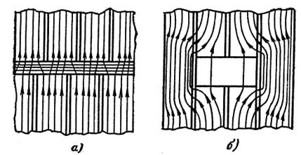
Fig. 8.9. Non-magnetic gap: a - in the butt magnetic
system b - in the charge magnetic system.
The area of \u200b\u200bthe gap (joint) P s is taken for straight joints equal to the active section of the rod Ps or yoke P1, for oblique joints P s \u003d √2 Ps.
The shape of the cross section of the yoke can affect the distribution of induction over the cross section of the yoke and the rod (see § 2.3). If the number of steps in the yoke section is equal to or differs by one or two steps from the number of steps in the rod section, then the distribution of induction in the yoke and the rod can be considered uniform and take the loss increase coefficient depending on the shape of the yoke section, k p, i \u003d 1, 0. For the yoke with the ratio of the number of steps of the rod and the yoke equal to three, k p, i \u003d 1,04; equal to six, k p, i \u003d 1.06 and for a yoke of rectangular cross section k p, i \u003d 1.07.
For pressing rods and yokes during assembly of the transformer core, its various structural parts are used. Depending on the power of the transformer, the pressing method can be selected in accordance with the recommendations of the table. 8.12. The same table shows the coefficients k p, p and k t, p to take into account the effect of pressing on losses and open circuit current.
Table 8.12. Methods of pressing the rod and the yoke and the coefficients k p, p and k t, p to take into account the effect of pressing on losses and open circuit current.
Some technological factors also affect idle loss. The longitudinal cutting of a strip of steel roll into tapes and the transverse cutting of a tape into plates result in internal mechanical stresses in the plates and an increase in the specific losses in steel. This increase can be taken into account by introducing a coefficient k p, p, which for annealed steel grades 3404 and 3405 can be taken equal to 1.05 and for unannealed 1.11. For annealed steel grades M4X and MbX k p, p \u003d 1.025 and for unannealed 1.05.
When cutting plates from a strip of roll on the cut line, burrs are formed. The removal of these burrs with knives leads to an increase in specific losses, which can be taken into account by the coefficient k p, s: k p, s \u003d 1 for annealed plates and 1.02 for unannealed ones. If the burrs are not removed, then k p, s \u003d 1,02 and 1,05, respectively. For plates with a width of more than 0.3-0.4 m k p, s \u003d 1.
Coating the plates with an insulating varnish film increases losses by k p, l \u003d 1 time during air cooling of the plates and by k p, l \u003d 1.04 times during water cooling.
Modification of the upper pit of the core during installation of the windings leads to an increase in losses, taken into account by the coefficient k p, w When the transformer power is up to 250 kV · A k p, w \u003d 1.01, at 400-630 kV · A - 1.02, at 1000-6300 kV · A - 1.04-1.08 and at 10000 kV · A and more - 1.09. The blending of the magnetic system into one or two plates in the layer affects the specific losses and is taken into account in table. 8.10. Due to the need to take into account the increase in losses in cold-rolled steel in the yoke angles, i.e., in the parts of the yokes shaded in Fig. 8.8, b, it is convenient to determine the mass of steel and losses in the magnetic system in this case in the following order.
The mass of the rods is determined by (8.11) (for the yoke e is the rectangular cross-sectional shape G c "" \u003d 0), and the losses in them are calculated, as usual, by the induction of the rod and the table data of the specific pc losses for steel of the used grade.
The mass of yokes is divided into two parts. The mass of steel parts shaded in Fig. 8.8, for a three-phase transformer it is six times and for a single-phase transformer - four times the mass of the angle G y, determined by (8.5), (8.6) or (8.7). The mass of the steel of the unshaded parts is determined as the difference G "i - 4Gy for a three-phase and G" "i - 2G y for a single-phase transformer. Therefore, the total mass of steel of two yokes can be represented for a three-phase transformer in the form
![]() (8.31)
(8.31)
for single-phase - in the form
![]() (8.31a)
(8.31a)
In that part of the yoke steel mass, which is determined by the difference, on the right-hand side of (8.31), losses occur, which are determined in the usual way by induction in the yoke and specific losses ρ. In the mass of steel corners, in addition to losses determined in the same way, additional losses occur, depending on the direct or oblique shape of the joints of the plates of the rods and yokes.
For a flat three-phase charged magnetic system of a modern three-rod design with a mutual arrangement of rods and yokes according to Fig. 2.5, d, assembled from cold-rolled anisotropic steel plates, pressing the rods with wedging with an internal winding or bandages, and yoke with yoke beams or half-band beams that do not have through studs in the rods and yokes, idle losses can be calculated according to (8.32). Such a magnetic system has four angles at the extreme and two at the middle rods.
The coefficient of increase in losses in the corners can be found by the formula
It depends on the shape of the joints in the corners of the extreme k p, y, cr and average k p, y, cf rods of the magnetic system, the coefficients for which are determined by the table. 8.11. The values \u200b\u200bof k n, y calculated for various combinations of the shape of the joints are given in table. 8.13.
Table 8.13. The values \u200b\u200bof the coefficient kп, у for a different number of angles with oblique and straight joints of the plates of a flat charge magnetic system for steel of different grades at B \u003d 0.9 ÷ 1.7 T and f \u003d 50 Hz.
* The combined joint according to Fig. 2.17, c.
The expression Σрз n з П З determines the loss in the zone of joints of the plates of the magnetic system, taking into account the number of joints of various shapes, the gap area П З for straight and oblique joints, the induction in the gap ВЗ, and the specific losses of Рz during this induction according to Table. 8.10 and partially 8.9.
For a single-phase transformer with a rod magnetic system according to Fig. 2.5, and the formula. (8.32) turns into the formula, (8.32a)
where k p, y \u003d 4k p, y, cr and can be taken according to the table. 8.13. When conducting a preliminary calculation using the generalized method of Ch. 3 it is desirable to have a formula that is more convenient at this stage of the calculation, but sufficiently accurate, to determine the no-load losses. The product of the coefficients in (8.32), taking into account the fact that losses in the gap zone, defined as Σрз n з Пз, comprise from 2 to 4% of total idle losses and can be taken into account by the corresponding coefficient, can be calculated in accordance with with the previous instructions in this section and replaced by a single coefficient k p, d. In this case, by (8.32) we obtain
where k p, d is a coefficient that takes into account additional losses caused by sharp steel, deburring, pressing of the magnetic system and re-flashing of the upper yoke, as well as losses in the gap zone, can be taken from Table. 8.14.
Table 8.14. The coefficient of additional losses kp, d in (8.33) for steel grades 3404 and 3405.
Notes: 1. For steel grades M4X and M6X, you can take the same coefficients.
2.When the yoke cross section is rectangular, multiply the coefficient obtained from the table by 1.07.
It should be noted that the thickness of the electrical steel from which the magnetic system will be assembled, according to GOST 21427-83, can differ from the calculated one within ± (6.5 ÷ 8.5)% for cold rolled and ± (8.5 ÷ 10)% for hot rolled steel. These deviations can cause some change in the duty cycle and induction in the magnetic system, which in turn will lead to a deviation of the actual idle losses from the calculated ones.
The deviation of the actual losses in the finished transformer from the calculated ones can also be a consequence of the instability of the quality of steel, a greater or lesser increase in losses due to mechanical stresses during plate preparation and system assembly and other reasons. The influence of these factors can be added or subtracted, but, as a rule, in a correctly calculated transformer, the deviation of the actual losses from the calculated ones is on average no more than ± (5 ÷ 8)%. Given these deviations, in cases where the limit value of the idle losses of the transformer is set, the design losses should be maintained within the limits of the GOST norm or technical specifications plus half the tolerance.
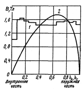
Fig. 8.10. Distribution of induction in the butt
spatial magnetic system: 1 - by
rod packages; 2 - for ring packages
(layers) of yoke.
According to GOST 11677-85 for idle losses in the finished transformer, a tolerance of +15% is set. Thus, in the calculation it is necessary to withstand the loss of idling within the limits of the norm corresponding to GOST plus 7.5%.
The spatial magnetic system according to Fig. 2.6, a, has its own characteristics in the distribution of magnetic flux in the rods and yokes, which should be taken into account when calculating the losses and open-circuit current. Due to the fact that the yoke of this system has a rectangular cross-sectional shape with a multistage section of the rod, as well as due to the unusual joining of the end surfaces of rectangular rod packets with different annular yoke packets (layers) (Fig. 8.5), an uneven distribution of induction over the rod and yoke cross sections (Fig. 8.10). The resulting additional losses, as shown by studies, can be taken into account when calculating losses by multiplying the losses in the rods by k p, n, s \u003d 1.04 and the losses in yokes by k p, n, i \u003d 1.26.
When the primary winding (HV winding) is connected to a star without a neutral wire, the 3rd harmonic no-load current cannot flow in the primary winding, which leads to the appearance of a 3rd harmonic magnetic flux in the magnetic system.
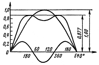
Fig. 8.11. The curve of the magnetic flux in the yoke
spatial magnetic system (1st and 3rd
harmonic, resulting curve)
This component of the magnetic flux is displaced from the parallel-connected rods into annular yokes, where its initial phase coincides with the initial phase of the 1st harmonic. As a result, the maximum value of the magnetic flux and induction in yokes decreases by 1.14 times (Fig. 8.11), which leads to a decrease in the specific losses in the yoke steel and is taken into account in the calculation by a decrease in the induction in yokes.
The induction in the rods in this case is calculated according to (8.28). The first harmonic induction in the straight sections of the yoke can be found by
![]() (8.34)
(8.34)
The maximum induction in the straight sections of the yoke, taking into account the 3rd harmonic in the jazz, is defined as
![]() (8.35)
(8.35)
The calculated induction in the corners of the magnetic system B y is taking into account the induction of the rods and straight sections of the yokes
![]() (8.36)
(8.36)
The appearance of the 3rd harmonic magnetic flux in yokes also leads to a distortion of the shape of the curve Ф \u003d f (t), an increase in the specific losses in steel and the total losses in yokes. This increase in losses is taken into account by introducing the coefficient k p, and to losses in yokes, which for spatial magnetic systems according to Fig. 2.6 we can take k p, and \u003d 1.33.
The manufacture of yokes by winding from a cold-rolled tape is associated with mechanical stresses on the material and significant residual deformations of the tape, which leads to a significant deterioration in its magnetic properties. Therefore, regenerative annealing of coiled yokes in long-acting furnaces is absolutely necessary. In the absence of annealing of the wound yokes, one should reckon with a possible increase in losses to twofold and with a significantly larger increase in the open-circuit current. The plates of the rods must be annealed in continuous roller table furnaces.
When calculating the no-load losses, the technological factor should also be taken into account, i.e., the increase in losses due to mechanical stresses on the steel plates after annealing during assembly of the core and the entire transformer, the imperfection of regenerative annealing, etc. This factor can be taken into account by introducing the coefficient k p , t, depending on various reasons, including the level of production culture of a particular plant. This coefficient can be taken k p, t \u003d 1,0b.
Based on the comments made, the formula for calculating idle losses in a spatial magnetic system can be represented as
The specific losses in the steel of the rods, the straight sections of the yokes and the angles of the magnetic system p c, p i and p y are determined by the table. 8.10 for steel of the corresponding grade by induction B s, B i and B y. The coefficient k "n, y is selected according to table 8.1 1 for the same steel with a direct joint.
When conducting a preliminary calculation according to the generalized method of Ch. 3, we can use the formula (8.37) in a transformed form
![]() (8.38)
(8.38)
where the coefficients k "c, k" i, k "y calculated according to (8.37) for steel 3404, induction in the rod B with from 1.5 to 1.65 T and for the 1st harmonic induction in the straight sections of the yoke B i \u003d (1.0 ÷ 0.9) V s, can be taken from table 8.15. For other steels, these coefficients can be calculated on the basis of (8.37) .In the coefficients k "c, k" i, k "y, in tab. 8.15, respectively, the specific losses p s, p i, p y are included.
Table 8.15. The values \u200b\u200bof the coefficient k "c, k" i and k "y in (8.38) for a spatial magnetic system. Steel grade 3404.
When calculating the no-load losses in the spatial magnetic system according to Fig. 2.6, b, consisting of three wound rings, it should be taken into account that in the calculated induction in the rod B with the 1st harmonic induction in the individual rings B k1 is 2√3 \u003d 1.15 times more (see § 2.1), t. e. B k1 \u003d 1.15 V s. In this case, a harmonic magnetic flux appears in each of the wound rings according to Fig. 8.12 and the maximum value of induction decreases by 1.14 times. Thus, the maximum induction, which determines the specific loss in steel, in such a magnetic system can be taken equal to the calculated induction In to \u003d In.
In this case, the distortion of the shape of the magnetic flux and induction curve can be taken into account by introducing the coefficient k p, and \u003d 1.33.
To take into account the technological factor, you can enter the coefficient k p, t \u003d 1,06.
Since the concept of angle does not exist in the magnetic system under consideration and the homogeneity of each ring in calculating the losses does not need to be divided into rods and yokes, the formula for calculating the losses in the final and preliminary calculation takes the form
![]() (8.39)
(8.39)
where the mass of steel of the magnetic system G article is determined by (8.26).
i 0a \u003d (P x / S) 100%,
Or, expressing rated power S in kwa,
i 0a \u003d (P x / 10S)%,
As for the magnetizing current i op , then its value at a certain value of induction, as well as idle loss, depends primarily on the grade of steel used and the design of the magnetic circuit. The calculation of the magnetizing power consumed by the steel of the magnetic circuit is performed similarly to the calculation of losses. Specific Magnetization Power Values q are taken according to the table compiled for each grade of steel based on experimental data. But since the main magnetic flux Φ along its path must also pass through the joints (gaps) between the plates, overcoming the resistance of the joints requires an additional magnetizing power, which will depend on the design of the magnetic circuit - butt or burdened, the magnitude of the gap, the charge pattern, and induction, of course. In domestic transformer manufacturing, exclusively charged magnetic cores are used, therefore, the tables contain the values \u200b\u200bof the specific magnetizing power per joint (gap) ( var / cm 2 ) specifically for such magnetic cores. Thus, the magnetizing current
i 0P \u003d (q CT G CT + q I G I + n CT q CT.3 F CT + n I q I F I) / 10S%
Where q CT and q I - specific magnetizing powers for rods and yokes, respectively var / kg; G CT and G I - the weight of the rods and yoke, kg;n CT and n I - the number of joints along the sections of the rod and yoke; q CT.3 and q I.3 - specific magnetizing powers per joint, var / cm 2 ; Fst.z and F I - section of the rod and yoke (excluding duty cycle), cm 2 . The number of joints for a three-phase magnetic circuit will be n ST = 3, n I \u003d 4 (Fig. 4.2). For large transformers, in which the magnetic circuit plates are made composite due to the long length, the number of joints increases accordingly. Specific Magnetization Power Values q for cold rolled steel can be taken from table. 4.1. To the value of the magnetizing current obtained by formula (4.7), collected from cold-rolled steel plates with straight joints, a correction factor is added to increase the magnetizing power in the corners of the magnetic circuit in the same way as when calculating the loss in steel. An increase in magnetizing power is caused by a decrease in the magnetic permeability of cold rolled steel in those parts of the magnetic circuit where the direction of the magnetic flux does not coincide with the direction of rolled sheets. For induction in the range of 1.5-1.7 t the magnification factor of the magnetizing power in the corners of the magnetic circuit is approximately 3 ÷ 3.5.
Fig 4.2. The position of the joints of the plates in a three-phase magnetic circuit.
The curve of the dependence of the magnetizing current gp on the magnitude of the induction (the curve of the initial magnetization shown in Fig. 4.3, a) has a so-called inflection point, near which steel saturation occurs. An increase in the induction by sharpening the kink of the curve causes a sharp increase in the magnetizing current, which is the main reason for limiting the maximum value of the induction of 1.4-1.45 t for hot rolled steel and 1.6-1.7 t for cold rolled steel. In addition, an increase in induction greatly distorts
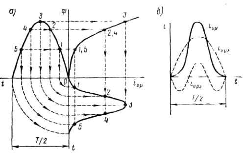
Fig. 4.3. Magnetizing current curve: a - plotting a curve from a given saturation point (3); b - decomposition of the non-sinusoidal curve into sinusoidal components of the first harmonic (i op1) and third harmonic (i op3)
The shape of the magnetizing current curve, which becomes non-sinusoidal (Fig. 4.3, b). As a result, conditions are created for the appearance of magnetic fluxes of higher harmonics, of which the magnetic flux of the third harmonic is especially unpleasant. In the star-star winding connection diagram (without a zero point), this flow, as coincident in phase in all three rods, is forced to close in the steel parts of the transformer structure (yoke beams, tank, etc.), causing additional, difficult to take into account losses in them.
i 0 \u003d √ i 2 0P + i 2 0a
For a three-phase transformer, the obtained value of the open-circuit current will be average for three phases. The actual value of the no-load current for the finished transformer for the middle rod will be less than for the extreme ones. This is due to the asymmetry of the magnetic system for different phases. The average length of the magnetic line of the middle phase B will be less than that of the extreme phases A and C. Since the active component of goa is relatively small, it can be assumed without any particular error that i 0 \u003d i 0P .

Fig. 4.4. Curves of specific losses and magnetizing power in steel grade EZZO
But in real transformers, this dependence in the range of applied values \u200b\u200bof induction is expressed more sharply, approximately in proportion to the third degree of induction, i.e., no-load losses strongly depend on the magnitude of the primary voltage supplied to the transformer. The curve of changes in specific losses in steel, according to the table. 4.1 is shown in fig. 4.4. The magnitude of the magnetizing current depends on induction to an even greater extent. Since, in order to save active materials, power transformers are designed with the highest possible induction values \u200b\u200bclose to steel saturation, a further increase in induction with increasing voltage causes a sharp increase in the magnetizing current. This can be seen in fig. 4.4, which shows the dependence of the specific magnetizing power q and q 3 from induction IN.
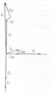 |
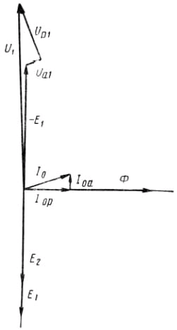
Fig. 4 5 Vector diagram of idle transformer
According to the second law of Kirchhoff, the geometric sum of e. d.s equal to the sum of the voltage drop in the circuit resistance, i.e.
Ú 1 + É 1 + É p1 \u003d Ú a1
Since the applied primary voltage Ú 1 should be balanced by the available in the chain e. e. and voltage drops, the equation of equilibrium (balance) e. d.s usually written as follows:
Ú 1 \u003d - É 1 - É p1 + Ú a1
E.s. Scattering - É p1 can be considered as a reactive voltage drop Ú p1 taken with the opposite sign. The equilibrium equation can be graphically presented in the form of a transformer idle vector diagram shown in Fig. 4.5. In this diagram, the vectors e are plotted along the vertical axis. d. s, and horizontal - the amplitude vector of the main magnetic flux F. Since e. d.s E 1 and E 2 lagging behind the flux Ф by a quarter of the period, then their vectors with a positive value are directed down. The same diagram shows the idle current vectors İ about and his active İ ooh and reactive İ op components. Active voltage drop vector Ů a1 coincides with the direction of the vector İ about , and the vector Ů p1 jet fall ahead of the vector İ about for a quarter of the period (90 °). Vector Ů 1 defined as the trailing sum of vectors - Ė 1 , Ů p1 and Ů a1 .
I 2 \u003d U 2 / Z 2
Where Z 2 - impedance circuit. Secondary current I 2 creates magnetizing force (ampere turns) I 2 ω 2 , which should excite in the magnetic circuit some magnetic flux f n. According to Lenz’s rule, this flow in the primary winding covering it will cause the primary magnetizing force I ’ 1 ω 1 equal in size I 2 ω 2 . According to the same rule, the magnetizing force creates a magnetic flux - Ф n, i.e. a stream equal and directed opposite to the stream Ф н. Magnetic fluxes cancel each other out, but a load current appears in the primary winding
I 1 \u003d I 2 ω 2 / ω 1
Thus, when switching on the secondary side of the load transformer, load currents appear in both of its windings, directed opposite to each other. In power transformers, without a large error, it is believed that the primary and secondary voltages are proportional to the number of turns of the windings, therefore
I ’1 \u003d I 2 ω 2 / ω 1 \u003d I 2 U 2 / U 1 or U 1 I’ 1 \u003d U 2 I 2
It follows that the primary and secondary powers are equal, and this is consistent with the law of conservation of energy. Transformer, consuming on the primary side electrical energy of one voltage U 1 gives the same energy (minus losses) from the secondary side, but only at a different voltage U 2 . Since there is also an open circuit current in the primary winding I 0 then the total primary current I 1 when the load of the transformer should be equal to the sum (generally geometric) of the load current I ’ 1 and open circuit current I 0 i.e.
İ 1 \u003d İ "1 + İ 0
But since the open circuit current is only a few percent of the rated load current and, in addition, both currents add up at a certain angle to each other, usually the open circuit current is neglected and it is assumed that I 1 ≈ I ’ 1 . Load currents I 1 and I 2 passing through the transformer windings cause active voltage drops in them U a1 \u003d I 1 r 1 and U a2 \u003d I 2 r 2 and inductive voltage drops P k1 and P k2 . Active voltage drops occur due to electrical (joule) losses in the windings equal to P K1 \u003d I 2 1 r 1 and R k2 \u003d I 2 2 r 2 . Winding losses R k1 and R k2 in total make up the bulk of the short circuit losses R to transformer. Inductive voltage drops occur due to the presence of magnetic fluxes scattering, covering each of the windings individually. Inductive voltage drops compensate for e. d.s scattering E p1 and E p2 i.e. U p1 \u003d - E p1 and U p2 \u003d - E p2 . In the given transformer, the total active voltage drop is equal to the sum of the active voltage drops in both windings, i.e.
U a \u003d U a1 + U a2
Similarly, the total inductive voltage drop is equal to the sum of the inductive voltage drops, i.e.
U p \u003d U p1 + U p2
In the vector diagram of the transformer, the geometric sum of the active and inductive voltage drops, the vectors of which are at an angle of 90 ° to each other, is the total voltage drop, called the transformer short circuit voltage U K, therefore
U k \u003d √U 2 a + U 2 p (5.1)
Losses and short circuit voltage are important operational parameters (characteristics) of transformers, therefore they are standardized by GOSTs. Their values \u200b\u200bare given above, in table. 2.1 and 2.2. The magnitude of the efficiency and changes in the voltage of the transformer, the calculation of which is given below, depends on the magnitude of losses and short-circuit voltage.
P \u003d I 2 r.
In factory practice, a converted formula is often used, which includes the current density δ and the weight of the winding wire G o ,
P K \u003d I 2 r \u003d δ 2 s 2 P ρ (1 / s P) \u003d ρδs P l.
Because G 0 \u003d γs P l 10 -3 and s P l \u003d G 0 10 -3 /γ then
P K \u003d (ρ / γ) δ 2 G 0 10 3 \u003d K П δ 2 G 0, Tue (5.2)
Where s P - wire section, mm 2 ; l- wire length m; ρ - resistivity of copper (or aluminum), Ohm mm 2 / m; γ - specific gravity kg / dm 3 ; G o - weight of the winding wire, kg. Coefficient value TO P taken from the table. 5.1.
Table 5.1
Since the current densities and the weight of the wires at the primary and secondary windings differ from each other, the losses in the windings are calculated for each winding separately and then summed.K f \u003d 1 + [(m 2 -0.2) / 9] (a ") 4, (5.3)
Where m - the number of layers of the coil; a" - reduced radial wire size equal to
a "\u003d (a / 1.03) √ (b / b FM) (f / 50) K P
a- radial wire size, cm ; b - axial size of the bare wire, cm ; b OF - the same, insulated wire, cm ; TO r - Rogowski coefficient ( cm . § 5.4); f- frequency Hz. For windings of a round wire of diameter d K Ф \u003d 1 + [(m 2 -0.2) / 15.25] (d ") 4, (5.4) where d " - reduced wire diameter equal tod "\u003d (d / 1.03) √ (d / d FM) (f / 50) K P
d OF - diameter of insulated wire, cm . With wire diameters up to 3.5 mm (large diameters are rarely used, usually in such cases they switch to a rectangular wire) the percentage of additional losses is relatively small, therefore, with round wires, the additional losses are neglected. When calculating the additional losses, it should be taken into account that their value in the layer of wires adjacent to the main scattering channel is approximately 3 times larger than the average value determined by the above formulas, which can lead to increased heating of this layer. In addition, due to the curvature of the scattering magnetic flux, local overheating can occur at the output of the winding with a large axial size of the wire, which must be taken into account when calculating the losses of high power transformers. From a consideration of the above formulas, it can be seen that the magnitude of the additional losses very much (to the fourth degree) depends on the radial size of the wire. Therefore, the use of too thick, massive wires should be avoided, and if it is required because of the need to have a large common section of the winding wire, then several parallel wires should be used with their transposition (movement) ( cm . further screw windings). In addition to the additional losses in the winding wires, the scattering fluxes also cause additional losses in the tank walls, pressing yoke beams and other massive parts of the transformer structure. These losses arise both from eddy currents and from magnetization reversal. The theoretical calculation of these losses is also very difficult, since the exact direction of the scattering magnetic field and its configuration are usually not known. For power transformers of size 1, additional losses in the tank walls R b due to their relatively small size, they are usually not taken into account. For transformers of higher power, there are several proposed empirical formulas for their calculation. For transformers of dimensions II and III, the simplest is the formulaP 6 \u003d 0.007 S 1.5 W (5.5)
Losses in the taps between the windings and the bushings (bushings) are part of the short circuit losses and must be taken into account when calculating the latter. Losses in the branches can be accurately determined after the design of the transformer, i.e. when the length and cross section of the branches are known. However, the magnitude of these losses is at least approximately desirable to know in advance so as not to make adjustments to the calculation of the windings after design development. The data of the bends of already completed serial designs of the power transformers of the same type in terms of power in terms of losses do not significantly differ from each other. Therefore, the preliminary value of losses in the branches R open a three-phase transformer with a sufficient approximation can be determined by the empirical formula
P hole \u003d 0.05I 4 √S W, (5.6)
Where I - linear current of the winding, a. As can be seen from the above formula, the quantity R open at a current not exceeding 100-200 ais relatively small, therefore, losses in the branches of power transformers of dimensions II and III are practically sufficient to determine only for LV windings.
Power loss power transformer consists of so-called copper losses and steel losses. The first are connected with the flow of the load current through the conductors of the windings having a certain electrical resistance. Losses in steel are caused by eddy currents, magnetization currents that occur in the magnetic circuit.
During idle experience voltage is connected to one winding, the other remains open. The power consumed in this case by the transformer from the network is spent more on magnetizing steel of the magnetic circuit, less on heating the winding conductors than can be neglected. Therefore, this experience allows us to measure the power loss in steel, called idle loss.
Additionally, by connecting to the remaining open winding, you can measure the voltage on it, and calculate the transformation coefficient from the readings of two. But this measurement does not apply to the idle experience itself.
The experience of XX during commissioning are:
All dry transformers, as well as liquid non-combustible dielectric as an insulating and cooling medium.
- Oil-filled transformers with a capacity of more than 1600 kVA.
- Transformers of own needs of power plants, regardless of their capacity.
In operation, such measurements are carried out only for transformers with a capacity of 1000 kVA or more, and only after major repairs associated with a change in windings or repair of a magnetic circuit. According to the network rules, it is possible to take measurements by order of the technical director of the enterprise after the chromatographic analysis of the gases dissolved in the oil gives alarming results. But this applies only to power transformers with windings of 110 kV and higher.

The order and scheme of measurement
Before the experiment, the process of demagnetization of the magnetic circuit of the tested transformer is carried out. For this, a direct current is passed through one of the windings of the low voltage side. The current is connected repeatedly, each subsequent connection occurs with a change in polarity and a decrease in magnitude. The initial value shall not be less than twice the expected idle current. With each subsequent inclusion, the value decreases by 30-40%. The process ends when the current is less than the value of the no-load current.
To conduct a direct idle test, a rated voltage is applied to the secondary winding of the transformer, with a deviation of ± 5% from the norm. The neutral output, if any, is not used. The voltage in this case is strictly sinusoidal, with the rated frequency of the network.
To carry out measurements, three laboratory devices will be required, with an accuracy class of at least 0.5. These are ammeters, and wattmeters. connected in each phase in series. turn on the line voltage of all three phases. The current windings of the wattmeters are connected in series with the ammeters. The voltage windings of the wattmeters are connected according to the above diagrams. Voltage is applied, readings are taken from the instruments.
Strictly speaking, the measurement is carried out according to the same schemes that were used at the factory for the experiment. After all, the data obtained will need to be compared with the factory ones. But, if the source of the three-phase voltage is not available, you can perform three measurements, applying voltage to the two phases of the transformer winding, shorting the third remaining free.
In this case, only linear voltage is used, since the distortion of the shape of the curve due to non-linear loads in the network has a minimal effect on it. According to the same schemes, an idle test is carried out at low (low) voltage.
Analysis of measurement results
During acceptance tests and overhauls, the data obtained are compared with the protocol on the relevant tests carried out at the plant after the manufacture of the transformer. A discrepancy of more than 5% is not allowed.
For single-phase transformers in these cases, the power loss should not differ from the original value by more than 10%.
In operation, only the no-load current is measured based on experience with a rated voltage or power loss at reduced. PTEEP does not normalize deviations from the norm.
However, if damage to the transformer is suspected, the method of measuring losses using three consecutive experiments gives a very valuable result. Since the transformer phase windings are in unequal conditions, it is possible not only to calculate whether there is a defect, but also to determine the defective phase.
The magnetic flux path during the excitation of the conclusions of AB and BC is the same. Therefore, the power loss for the experiments in these phases will not differ. When the AC phases are excited, the path covered by the magnetic flux is longer, therefore, the power loss will be 25-50% higher than the previous ones. Comparing these indicators, you can identify at what phase there is a defect.
|
transformer |
Voltage |
Power |
making |
Idle losses |
|
|
catalog |
measured |
||||
For example, we give the total losses in large block and network transformers for different voltages (according to the company Renzmann & GruenewaldGmbH, Germany) (Table 2).
As a result of measures taken in the European transformer industry on the basis of improving the design and materials, no-load losses for a conventional 220 kV transformer with a capacity of 200 MVA have more than tripled over the past 50 years, and load losses have halved.
Table 2.
|
Block transformers |
Network transformers |
|||||
|
Power, |
Stress |
Power, |
Stress | |||
Idle lossescause damage several times greater than load loss, making up the bulk of capitalized losses. The loss of idle losses is especially significant for transformers of lower power. So, if for a modern 500 kV transformer with a capacity of 1000 MVA, the loss is about 0.035% of the total power, then for an 11 kV transformer with a power of 1 MVA this is 0.35%. The main damage to the energy sector in terms of losses is caused by distribution transformers. Significant efforts of foreign firms are directed to their improvement, reduction of idling losses. For large power transformers, the generation of heat loss creates big problems due to the high degree of use of active materials and the desire to reduce dimensions. Heat generation complicates the cooling system and largely determines the design of the transformer.
Main reason idle losses stroke are losses in steel from magnetization reversal, losses from eddy currents in plates of steel, from scattering fluxes in other parts of the transformer. Load losses include losses in the copper of the windings, losses from eddy currents occurring in the massive parts of the transformer lying next to live parts, losses from scattering fluxes.
Reduced idle losses can be achieved by:
use for the core material with significantly reduced losses on magnetization reversal and eddy currents;
optimization of core design and manufacturing technology;
designing a transformer core for low-induction operation.
The quality of electrical steel is being improved continuously. For widely used grades of cold-rolled, oriented, with high magnetic permeability, steel with a high silicon content abroad, a specific loss level of about 1.05-1.10 W / kg at 50 Hz and 1.7 T was achieved 10-15 years ago. The best grades of steel have a specific loss of about 0.85 W / kg. The use of sheets of smaller thickness also reduces losses. Thus, steel with a thickness of 0.23 mm, which is increasingly being used abroad, has a specific loss of 20% less than steel with a thickness of 0.3 mm.
An effective technology for processing steel is laser scribing with a decrease in the length of oriented crystals. In this way, in combination with the use of plates of reduced thickness, a specific loss level of 0.5 W / kg was obtained. With a decrease in sheet thickness to 0.18 mm, a decrease in specific losses to 0.3 W / kg is predicted.
Amorphous steels are being actively developed. Compared with ordinary steel, losses in them are 3-4 times less. The main producer of such materials is AlliedCorp Corporation. (USA), producing amorphous steel Metglas.
For Hitachi transformers with Metglas cores, idle losses are 20% less than normal. The most widespread such transformers are in the USA and Great Britain.
The use of amorphous steels does not yet replace oriented electrical steel. Extreme brittleness interferes, the thickness of the tape is not higher than 20-30 microns, high sensitivity to mechanical stress during processing.
Noise reduction requirements limit the use of high magnetostrictive steel. Steel with a silicon content above 6.5% is unacceptable for this reason, and even at 4% it is difficult to roll steel due to its high brittleness. Only rapidly cooled steel has less brittleness, but its processing at high temperature does not allow obtaining structures with such high magnetic characteristics as normal steel with an oriented structure. The optimal thickness of the plates according to recent studies is 0.1 mm (at 1.8 T).
Recent developments in the field of transformer construction are based on steel with a silicon content of 3%, which has low magnetostriction and permissible losses. The use of reduced induction in the heart can not only reduce losses in it. but also significantly reduce the noise level from the transformer. The decision is made on the basis of technical and economic considerations.
Design and technological measures to reduce core losses:
the use of tape ties of cores and yokes using fiberglass bandages, eliminating the need for holes for coupling bolts - places of loss concentration;
shearing of cores with a shift (oblique joint), which has become possible with the use of a computer to control the cutting of steel, a combined charge with a partially oblique joint is also used;
careful manufacture of individual steel sheets;
assembly, blending of the core, eliminating gross mechanical effects on steel plates.
Load lossare determined by the currents flowing through the windings and include losses on the active resistance of the conductors of the windings, losses due to eddy currents in the conductors, losses due to eddy currents in massive parts of the transformer lying near current-carrying parts.
In foreign practice, copper has almost completely replaced aluminum due to its low resistance and high strength - this reduces losses and increases the reliability of the transformer.
Since the eddy current loss in the conductor is proportional to the square of its cross section, reducing its cross section by 33% reduces the loss by more than 50%. This has been successfully used to reduce load losses in the transformer. Reducing the cross section of conductors is achieved by using ribbon cables that are twisted from several thin conductors. Improving the filling of the magnetic circuit window when using a ribbon cable for the US-developed series of transformers 141 - 500 kV with a power of 25 - 250 MBA allowed to reduce the weight by 6-15% , loss of idling by 8-15%, load loss by 3-22%. The winding is made of a ribbon cable, which is a bundle of foil tapes isolated from each other.
Reducing eddy current losses allows the use of wires with continuous transposition. To increase their mechanical strength, an epoxy coating of elementary conductors in the rod and rod baking during drying of the winding are used.
In LV windings, they try to use a transposed wire without additional insulation for better cooling.
The desire to reduce losses forces to improve methods for their calculation and optimization of the design of the transformer. Calculation of losses is a difficult task because of the need to determine the fields in active and passive nodes of complex configuration and the eddy currents caused by them.
An example of such work is the research of a transformer manufacturer in Egypt (ELMACO plants) and a number of universities in this country. The direction of work is to increase the accuracy of methods for calculating losses due to eddy currents in the transformer windings and in its tank from scattering flows.
Based on a three-dimensional field analysis using the finite element method, a set of programs has been developed for calculating the optimal design of transformers.
When calculating the losses in the windings, the dimensions of the core window, induction in the core, and the thickness of the conductors in the windings are taken into account. Losses in the tank determine the magnetic load of the core, the thickness and configuration of the walls of the tank, the distance from the tank to the active parts, the magnetic and electrical properties of the material of the tank.
Superconducting Transformers. A fundamentally new way to reduce losses in the transformer is the use of superconducting materials for windings.
The low-temperature superconductors on which the first prototype transformers were made are uncompetitive with high-temperature superconductors (HTSC). The progress and the creation of HTSC materials allows us to consider the economic prospects of such developments undoubtedly. From 1992 to 2000 the price of HTSC materials has decreased by 20 times!
Advantages of HTSC transformers: reduction of load losses by 90%, weight reduction up to 40% , short-circuit current limitation, reduction of reactance, overload capacity - 100% for a long time, low noise level. With mastered production, such a transformer is 20% cheaper than conventional of the same capacity.
According to calculations, a HTSC transformer with a capacity of 30 MB A will have a mass of 20 tons and will not have oil, whereas a conventional one has a mass of 45 tons, including 23 tons of oil, "es": ["W5G2KbNw1LU"], "pt": ["vmwyCKACUuc", "PZCvCTpeTsU", "PZCvCTpeTsU"], "fr": ["vgkE_nFia3o", "vgkE_nFia3o"], "la": ["GjdTrDOLKQg", "MR" BJJWR ])
From internal pipelines, drains are transported by external ...
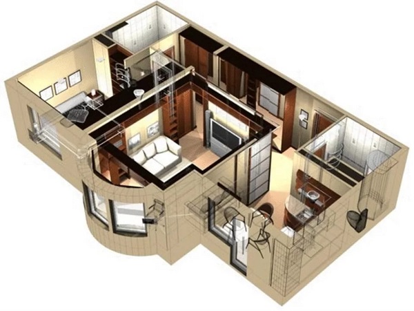
Each apartment, like every family, has its own characteristics, so it is difficult ...