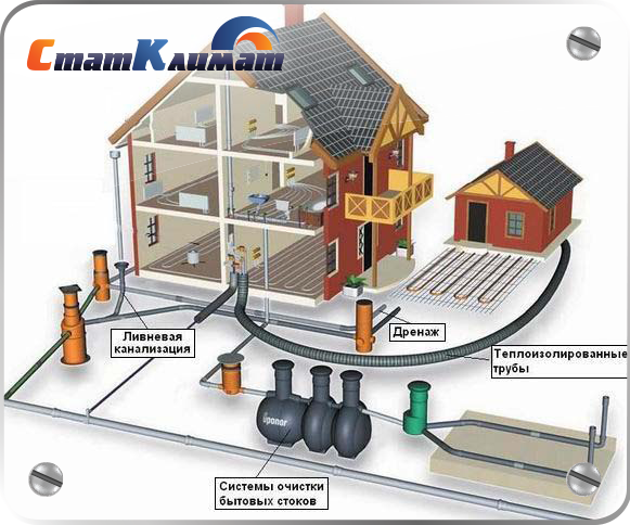
From internal pipelines, drains are transported by external ...
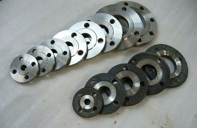
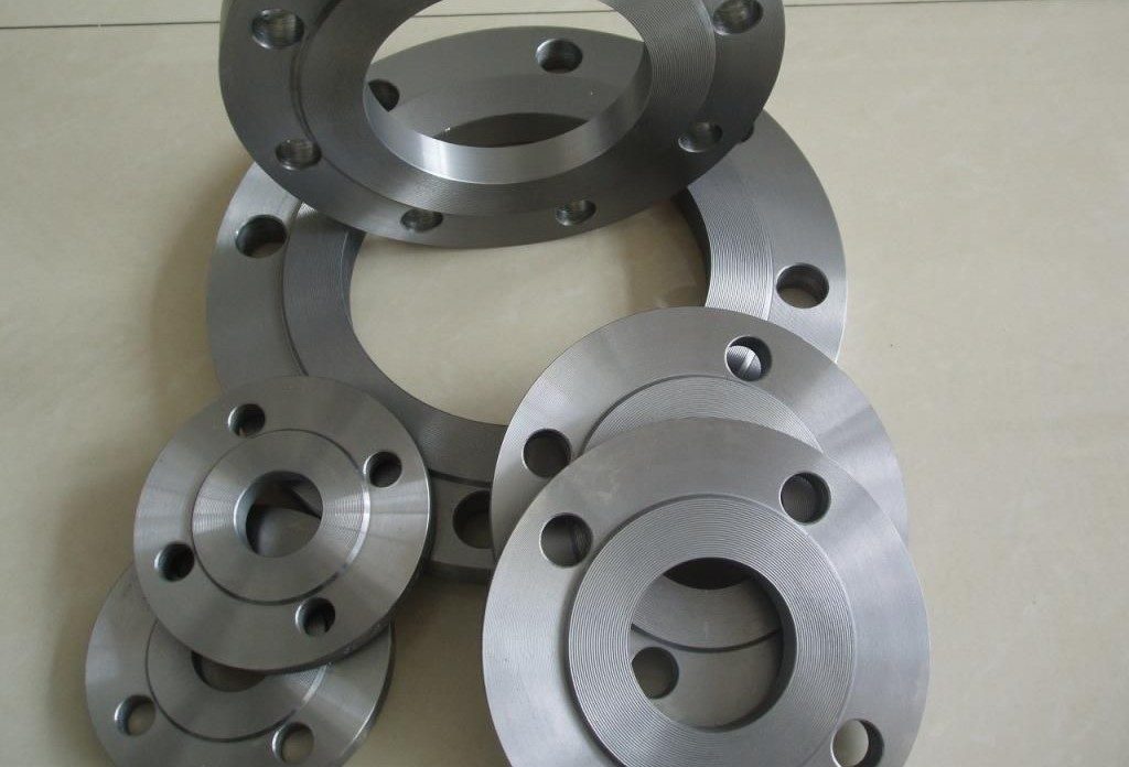
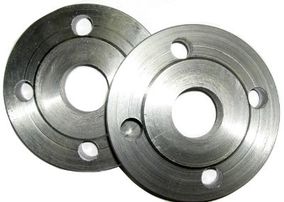
A flange is an assembly connection in the form of a ring having different thicknesses; its standards are controlled by GOST. This part is used during installation of pipelines and fastening of special equipment. With the help of flanges, all nodes and assemblies located throughout the trunk system are connected.
The pipeline element used in the installation of individual sections and equipment to any storage system is called a flange. It can be attributed to auxiliary fittings, since it is a connecting part between pipes.
With the help of flanges, all nodes and assemblies located throughout the trunk system are connected. Use them as a regulating link for connecting pumps and other automation. A flange is an assembly connection in the form of a ring having different thicknesses; its standards are controlled by GOST.
This part is used during installation of pipelines and fastening special equipment, which is used in many special areas. The production of flanges comes from those materials that enable their use in the intended environment.
The difference and their marking occurs according to the design. Among many countries, including the Russian Federation, 3 flange standards are very popular:
This GOST applies to all types of flanges and their auxiliary parts. In addition, the standards apply to the connecting elements of devices, machines, tanks, pipes, as well as the temperature and conditional pressure.
In addition, the flanges can be intended for connecting work on the assembly of equipment and pipe flows.
At the moment of joining, the so-called flat flanges are put on the connecting part of the pipe and are welded to the system with two seams. In this embodiment, the pipe flange may have only 1 welding seam. GOST free flange consists of two parts: the ring and the product itself.
Two connectors are easy to install. The ring is welded to the base, and the flange itself is able to move freely for quick connection with bolts. Such fastening is carried out in poorly accessible places and with frequent repairs flange joints.
Among many varieties, there are such models of flanges:
Many types of products find their application in the oil industry. The most common types of flanges:
All listed flanges have their own tested surface, except for the free rotation model. Details that have a special purpose cannot be overlooked. These include the following items:
To connect asbestos-cement, steel and cast-iron products, a crimp flange is used, which by its fixation provides excellent sealing of the system. The flange is characterized by the presence of a rubber sleeve and the length of the fitting, which ensures the sealing of 2 chambers and the distribution of forces directed to the end of the pipeline. Such a pipe flange provides a guarantee that the hermetic connection will be flawless.
A wide variety of materials are used to make flanges. A common source for their production is carbon steel. Inside, the flange may have an identical coating, but different from the resource used. Such products are called lined flanges.
Choosing the type of product, we determine the material necessary for it. Usually the manufacture of fasteners depends on the material of the pipe itself. From the shape we invented and the surface prepared, it will be clear where to place the seal ring and gasket.
The connecting parts are:
The connection of pipelines through the flanges is considered a profitable and convenient invention.

Today, the installation of such a fastener is in great demand. There are a huge number of aspects at the time of selection of compounds. Such a question is best resolved by a knowledgeable specialist.
To connect the flanges, it is necessary to prepare the bolts. Their presence should be determined by the number of holes located in these blanks, and the dimensions and the required diameter of the bolts must be determined taking into account the involved parts for their fastening, and the pressure that is in the line.
Among the fasteners can be used studs, which are equipped with a shaft and nuts on both sides. More affordable is a simple hexagon and nut with the appropriate thread. The required parameters of fasteners are determined by GOST.
For hermetic connection use gaskets. They can be presented in the form of rings or compressed sheets that can ensure that liquid does not penetrate at the junction of pipes or connecting units. They make gaskets from metal and other materials. During installation of the gasket, the norm and the established rules must be observed. The main thing is to prevent leaks at the joints.
To achieve complete sealants in the fastener connection, you must have the exact components. Before you start the connection process and avoid unforeseen problems, you must do the following:
Despite which tightening method will be used, it is necessary at the very beginning to carefully prepare all the necessary parts and check for professional compatibility.
The use of flanged joints in pipelines is due to the ease of assembly and the possibility of replacement stop valves or shaped products. This design provides a solid connection of parts of the pipeline.
Thanks to flange connections, the following measures are facilitated:
Visually, the flange is a part with a flat surface of a square or round shape. The product has holes designed to install fasteners - bolts, studs, washers, nuts.
In the operation of pipelines several types of flange connections are used:
Flange connections are used for almost all pipelines with different media. Depending on the characteristics of the transferred medium, materials are selected for the manufacture of flanges or composite products are made that increase the resistance of metals to special substances.
Installation of a flange connection is carried out using fasteners and welding. The connection kit has several components:
Flange fasteners consist of several elements - studs or bolts, washers (engravers) and nuts. Fasteners are made of various materials and are used for a specific type of flange, taking into account the diameter of the hole, expressed in millimeters. Threaded connections have regulatory parameters for thread pitch. Metric type is expressed in millimeters, inch is defined in inches. Requirements for fasteners are established by regulatory documents and state standards.
When installing flanges, fasteners are used:
Flange joint kit parts have unified parameters that meet national and international standards. In our country, GOST standardization is used, DIN operates in Europe, and the American ANSI / ASME system is applicable for a number of countries (Japan, USA and others).
A clear classification of flanges allows the use of connection elements in various countries without additional adjustment of parameters. Differences in the classification of designations in standards are easily resolved by using translation tables.
Along with standard products, there is a need for flanges having non-standard diameter sizes, fastener locations. Parts made to special orders may have protrusions, additional holes or grooves. Products are manufactured according to individual orders and drawings, allowing to solve narrow technological problems.
The main element, the flange, is mainly made of steel (carbon, low alloy, stainless) and cast iron (malleable and gray type). Less commonly used are polypropylene, titanium, aluminum, bronze, and brass. The use of polypropylene has found distribution only in recent years. Installation is mainly carried out for polymer pipes.
Requirements for the product material (brand) are determined temperature condition, pipeline pressure and other parameters. Tables of the dependence of the metal grade on pressure and allowable temperatures are set by the standards in GOST. In the standard version, in the production of flanges, a material identical to the composition of the pipeline or the installation locations of the products is used.
Special requirements are imposed not only on the material for the manufacture of flanges, but also on the sealing elements of the connection. Gaskets provide tightness. For their manufacture, technical rubber with various characteristics is used: resistant to acids, alkalis, oils, gasolines, and elevated temperatures. The type of gasket and material is determined by the purpose of the pipeline and the characteristics of the connection. Less commonly used materials: wound, fluoroplastic or asbestos board.
In the manufacture of flanges, several methods are used:
The most productive method, often used to produce a serial batch, is stamping, carried out in closed forms - stamps. The least expensive is the method of cutting sheet metal parts. The method requires additional ultrasonic monitoring for the absence of caverns.
In the manufacturing process of parts, regular quality control is performed. The performance of highways depends on the quality of the flange, in the event of failure of which or accidents the user will incur significant losses. One of the main tests is checking for mechanical integrity and evenness of the surface.
Currently, a large number of imported equipment is being purchased, adapted to international standards. The enterprises have launched production of “transitional type” flanges, combining the parameters of different standardization systems.
To protect flange connections from aggressive environments, flanges are coated with special materials that extend the life of the flange. The surface layer of steel is treated with nickel, chromium, zinc and other materials that prevent premature destruction. The type of coating is determined by the customer.
In Russia, 3 types of connecting flanges of pipelines are used, which differ structurally. Parameters are established by state standard specifications. The type classification used for steel flanges used is included in several standards:
GOST standardization adopted in relation to threaded flanges, insulating types for underwater pipelines and others is less often used. These forms of pipe connections have a special purpose and are rare.
As part of the requirements of GOSTs, the features and parameters for each type of flange are determined:
It is measured in millimeters and indicates the difference in diameters of the connecting part and the pipe. The parameters do not match and are relevant for flat steel flanges and elements with a welded ring. For collar types of joint parts, the parameter does not matter. For conditional passage, the designation of the remote control is used using the indices A and B, where the letter A means the diameter of the part, and by B the pipes are expressed in millimeters.
The parameter sets the differences in size between the connecting holes. In some cases, various diameters, expressed in millimeters, are used for the holes. In the manufacture of parts, the standard version is used, which is the default for row 2.
The indicator expresses the maximum allowable pressure that can withstand the connection without leakage and damage. The parameter is affected by the type of part, material of manufacture, diameter, width of the connecting surface. Physical parameters and their influence on the maximum pressure indicator are established by GOST. When using the data, differences in the dimension of the pressure designation are taken into account.
The parameter is necessary to determine the pressure limit value. The physical interdependence of the pressure and temperature of the transported liquid should be taken into account when high-temperature media pass through pipes. The linear interpolation arising by calculation affects the flange connectivity, which decreases with increasing operating temperatures. GOSTs establish the relationship between temperature and pressure for each type of flange.
One of the important aspects of the flange mounting process is the fitting of all connection elements. Prior to installation, measures are taken to prepare the parts for installation.
At the preliminary stage, the following actions are carried out:
Trial gasket installation. When re-installing, used gaskets are not used. If it is not possible to use new seals, several old ones are used.
By tightening the bolts using a certain periodicity scheme, the joint strength and the tightness of the system are achieved.
When installing the bolts, the following scheme is used:
If there are 4 holes for bolts, the installation is made crosswise. During installation, uniform tightening of the locking elements is achieved. If the voltage is excessive, rupture of the threaded joint or breakage of studs, washers and bolts may occur. The required tightening force is specified in the specification.
In the process of mounting and tightening parts, tools are used: a manual wrench, hydraulic wrenches, a pneumatic wrench. Manual tightening of the fasteners requires practical skills. After a day, the technician re-tightens the fasteners.
Flange connections are used in plumbing, as well as when working with pipelines of various profiles. Due to their bulkiness and large weight, it is more reasonable to use them on large pipelines. For example, in industrial construction, as well as on the central highways of domestic supply systems.
Exist different types flange connections. All of them are standardized by the corresponding GOST. They differ in size, shape, type of connection and many other features. In this article we will consider the most popular flange connections, give them a characteristic and highlight the main nuances.
Flange joints are used to form steel and metal piping joints. The execution of flanged connecting units on steel pipes is predominantly permissible, since they have sufficient strength and reliability.
It should be noted that steel pipes and pipelines are characterized by large diameters. And flanges, due to their size and type of bonding, it is reasonable to put only on a variety of relatively large pipes.
Their implementation imposes some restrictions on the method of application. It is not that these types of joints could not be used on pipe samples of smaller diameter (up to 50 mm), but this is not always reasonable and too costly.
Insulating flange connection is too expensive and durable. Its use on side branches of pipelines is not a necessity. For these pipes, the distillation conditions of the support are greatly facilitated.
Inside household steel pipelines of small dimension (with a diameter of up to 50-80 mm), as a rule, the working medium is kept at a low pressure.
In addition, the current GOST also recommends installing flanges only where necessary. This means that for household pipelines of small diameters, simpler types of joints should be used, for example, standard threaded or compression couplings, conventional welding, etc.
As for the normative documents themselves, the main document is of course GOST. GOST - the state standard, applies to all pipe and pipe connections. There is GOST for flanges. GOST for flanges is number 12820-80. This is GOST for welded steel flanges with a protrusion.
There is GOST for products of another type. The 12820 brand is also present in their license plate, but at the end it already contains not number 80, but some other one. For example, 12820-50, etc.
The number by which you can see GOST (in our case 12820-80) is easily located on the Internet. The same GOST 12820-80 is on the network in free access. You can download and view it at any time. It shows all product sizes, the calculation of flange connections of a particular type and a bunch of other useful information.
We will deal with the design of flanges for pipelines. The design of the flanged connecting units largely depends on which particular sample we have in mind.
If you look at the usual types, we see that they have several similar details. The flange itself consists of several components.
Its main part is the puck. Washers for flange connections are made of steel round billets of a certain diameter. The washer has a large hole in the center.
The diameter of the hole is equal to the diameter of the pipes themselves. If we consider a sample of pipes with a diameter of 50 mm, then the inner diameter of the washer for flange connections will be similar. As a result, the execution of connections from flanges is greatly simplified. As well as the selection of a suitable sample.
So, the washers for flange connections have a hole in the center, in addition to the central passage, the connecting flange is equipped with several additional holes for the clamps that are located on its circumference.
This refers to a bolt or stud. A bolt or stud is pushed into the hole on the flange and then tightened with bolts.
Sometimes flanges are equipped with a special protrusion. It is designed to fix the outer part of the washer on the pipe. The type of fixation and its execution is selected separately, depending on the type of future connection.
The execution of flange connections implies the use of two such parts. They are called reciprocal. Mating flanges are completely identical to each other. They are mounted on the edges of steel pipes, which must be fixed together.
Installation is carried out by threading or welding washers with a protrusion to the pipe.

Then one connecting flange is brought to another and tightened with clamps. As clamps, as we noted above, a stud or bolt is used. There is no serious difference between them. You must have seen the bolts hundreds of times already. The connecting flange uses large bolts with a diameter of 10 mm or more.
The stud is like a bolt. It differs in the absence of a head. The stud, in fact, is a small steel rod with an external thread. The thread on it is cut longitudinally and completely covers the surface of the product.
A hairpin is convenient in that it is possible to tighten the flanges on both sides using two nuts. As a result, the strength of the connection increases, as well as its mobility.
The stud is removed in the same way as it is fixed - by loosening one of the nuts. An example of studs can be seen by looking at the design of the joints in any of the gas pipelines. On them, in most cases, a pin is used as clamps.
Due to the tightening by fixing bolts, the flanges allow hermetically connecting any pipe segments, while making them easily accessible for repair and modification. Such a connection is distinguished by the highest strength (unless of course the stud or bolt is tightened properly) good tightness, reliability.
That is why flanges are used so often when creating industrial pipelines. An alternative could be welding, but the welded part can no longer be removed.
It is worth considering such a thing as an insulating flange connection. For household pipelines, emphasis is placed on structural strength, the quality of connecting seams and parts.
However, it is also important to isolate individual parts of the system from each other. Indeed, the execution of steel supply systems implies that they are assembled from steel billets, and steel perfectly conducts current.
To avoid the occurrence of dangerous situations, ICs or an insulating connection were used. In general, IP is a method of fixing pipes, which allows the use of a connecting element with a special gasket or something similar, without reducing the final strength of the pipeline.
Gasket in the IP plays the role of an insulator. It is because of it that IS is able to separate individual pipe branches from each other. The current, if one is formed in the system, passes through the pipe, enters the insulating connection (IC), and then is extinguished on the same gasket.
The result is a system protected against electrical discharges. Installation of several ICs virtually eliminates the possibility of accidents due to the passage of current through the pipes. At the same time, their strength and tightness are not violated in any way.
The standard insulating connection is marked with an IP with a specific number. For instance:
The second digit in the marking indicates the diameter of the joint.
IFS is an abbreviation for abutment flange connection. The design of the IFS is almost completely consistent with the design of the IP.
Except for the fact that IFS mainly use rubber gaskets between the flanges. The presence of gaskets increases the strength of the final connection, without complicating the overall design.
The simplest example of an IFS is insulated flanges, between which a rubber dielectric gasket is placed. The washers are tightened with studs, thus fixing the gasket. In the event of a discharge, it will be extinguished at the moment of contact with the IFS.
IFSs are similar to IP labels. Only the calculation of flanged joints of an insulated type should be carried out more carefully.
Example of marking IFS flanges with a protrusion:
As you can see, there is practically no difference. But there is an important detail. The number in the marking may not correspond to the exact size of the inner diameter of the washer.
For example, IFS-108 has an inner diameter of 100 mm, not 108. Part IFS 50 has an inner diameter of not 50 mm, but 41 mm. And the IFS-80 part, respectively, has a diameter of not 80 mm and 71-72. Specific values \u200b\u200bare determined by GOST.
The execution of compounds of this type rarely leads to any difficulties, but there are all sorts of situations.
For example, a compression joint does not always provide the necessary strength and tightness: gaskets can loosen in it. And the strength and reliability of the pipeline is the most important parameter when it comes to industrial systems.
In such cases, accelerators are used. Accelerators - allow you to "disperse" or push the flanges a small distance without completely disconnecting them from each other. That is, it is now possible to seal a compression or any other connection without fully removing the washers, which you will agree is very convenient.
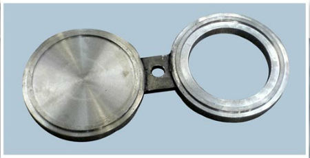
Another interesting device is the shutter. Obturators are mobile plugs of temporary and permanent type. Obturators consist of two round washers fastened in parallel. One washer plugged, the second open. The shutter is placed between the flanges.
In open form, it does not interfere with the flow in the system. In the closed one, the compression pressure in the pipeline drops and the flow movement is blocked.
The strength of the valve is such that it is permissible to leave it closed for several months without fear. Sealants are mounted on both compression and welded flange joints.
The diameter of the obryurator must correspond to the inner diameter of the pipe. If it is equal to 50 mm, then, accordingly, it can only be placed on a pipe with a nominal passage of 50 mm.
Flange connections consist of:
Actually flange;
set of fasteners (studs, nuts, washers);
gaskets (paronitic, fluoroplastic, thermally expanded graphite, steel, etc.).
The flange connection is convenient for installation and is in great demand. There are a large number of aspects of the selection of flange connections, for questions about which it is worth contacting only specialists.
What is a flange and what is it for? A flange is a part of a pipeline designed for mounting its individual parts, as well as for attaching equipment to the pipeline.
Areas of use The flange is used in the installation of pipelines and equipment in almost all industries. A variety of materials of which flanges are made today allows you to use these products as pipe fittings under virtually any environmental conditions (temperature, humidity, etc.) and in accordance with the environment passing through the pipeline (including aggressive) .
Distinctive features and characteristics of flanges
There are certain characteristics of flanges:
1. Constructive. The basis of this group of characteristics is the design of the flange. In the territory of the Russian Federation and the CIS countries, three flange standards are most widely used:
GOST 12820-80 - flat steel weld flange.
GOST 12821-80 - butt weld flange.
GOST 12822-80 - steel free flange on a welded ring.
Flanges according to the three most common standards mentioned above are designed to connect pipe fittings and equipment. Due to the design features, the mounting conditions of these flanges are different.
Steel flange flat welded.During installation, the flange is "put on" on the pipe and welded with two welds around the circumference of the pipe.
Butt weld steel flange.Installation of such a flange in comparison with a flat welded flange provides only one connecting weld (it is necessary to connect the butt end of the pipe and the “collar” of the flange), which simplifies work and reduces time costs.
Steel loose flange on weld ringconsists of two parts - a flange and a ring. In this case, of course, the flange and ring must be of the same conditional diameter and pressure. Such flanges differ in comparison with the above-mentioned ease of installation, since only the ring is welded to the pipe, and the flange remains free, which allows easy connection of the bolt holes of the free flange with the bolt holes of the valve flange or equipment without turning the pipe. They are often used in the installation of pipe fittings and equipment in an inaccessible place or in the frequent repair (inspection) of flange joints (for example, in the chemical industry).
In addition, it is positive that when selecting free flanges for a stainless steel pipe, in order to save money, it is allowed to use a stainless steel ring and a carbon flange
Flange Types The most used flanges in the oil and chemical industries:
with a neck for welding
through flange
welded with hollow for welding
welded lap (free-wheeling)
threaded flange
flange plug
When calculating flange joints take into account the following types of loads:
Tightening force of bolts (studs);
Internal or external pressure;
External axial force;
External bending moment;
The efforts caused by the constraint of temperature deformations of the elements of the flange connections, including flanges, bolts (studs) and a tube sheet or embedded part sandwiched between the flanges.
The filtration equipment according to the principle of action can be divided into two main groups:
Classification of filters. The devices in which the filtering process is carried out are called filters. Filters are distinguished depending on the mode of action. periodic and continuous actions. Depending on the type of pressure that creates the driving pressure necessary to push the fluid through the pores of the filter septum, there are:
filtersoperating under the influence of hydrostatic pressure of a column of filtered fluid;
vacuum filtersoperating under vacuum created by vacuum pumps;
filter pressesoperating under pressure generated by pumps or compressors.
Depending on the type of filtering partition, all filters can be divided into several groups:
filters with an unbound or granular septum;
fabric septum filters;
filters with a fixed rigid partition.
The choice of this or that filtering partition is caused by a number factors; the most significant are the chemical properties of the filtered fluid, the working pressure at which the filtration is carried out, the degree of fragmentation of the solid particles of the filtered mixture and, finally, the required performance.
The filtration cycle consists of the following operations: preparing the filtrate, filtering, washing the precipitate, unloading the precipitate.
The performance of the filter depends mainly on the thickness of the sediment and increases with its decrease. In this regard, it is necessary to remove sediment more often so that its thickness does not increase. However, frequent removal of sludge is associated with frequent repetition of work cycles and an increase in auxiliary time, therefore, it is necessary to establish the optimum performance of the filtering cycle when maximum productivity is ensured.
Periodic filters include:
a) Nutsche filters;
b) Druk filters;
c) frame filter presses;
d) chamber filter presses;
e) sheet filters.
Periodically operating filters: a - nutsche filter; b - druk filter
Continuous filter characterized in that the suspension is supplied, the sediment is removed or the condensed suspension is discharged continuously. In periodic filters, the continuity of operations is violated
are divided into the following types: filters with direct filtration; filters with preliminary sedimentation (with horizontal and vertical arrangement of filtering elements); filters with mechanical and hydrodynamic removal of sludge from the filtering surface and removal of sludge from the filter
Continuous Filters work, as a rule, under vacuum,
Continuous Filters characterized in that the stages of filtering, washing, drying, removing sediment and others are carried out on them sequentially and simultaneously. For this, the filters are equipped with special devices that regulate the sequence and duration of each stage of the process.
Continuous filters include:
a) drum vacuum filters;
b) pressure filters;
c) disk filters;
d) belt filters;
e) disk-type vacuum filters;
e) carousel filters.
Adsorption (lat. Ad - on, at; sorbeo - absorb) - an increase in the concentration of solute at the interface of two phases (solid phase-liquid, condensed phase-gas) due to uncompensated forces of intermolecular interaction at the phase separation. Adsorption is a special case of sorption; the reverse process of adsorption is desorption.
The absorbed substance, which is still in the volume of the phase, is called the adsorbent; the absorbed substance is called adsorbate. In a narrower sense, adsorption is often understood as the absorption of an impurity from a gas or liquid by a solid substance (in the case of gas and liquid) or by liquid (in the case of gas) as an adsorbent. In this case, as in the general case of adsorption, the impurity is concentrated at the adsorbent-liquid or adsorbent-gas interface. The reverse process of adsorption, that is, the transfer of matter from the interface to the phase volume, is called desorption. If the rates of adsorption and desorption are equal, then they talk about establishing adsorption equilibrium. In equilibrium, the number of adsorbed molecules remains constant for an arbitrarily long time if the external conditions (pressure, temperature and composition of the system) are unchanged
The nature of adsorption. forces m. very different. If these are van der Waals forces, then adsorption is called. physical, if valence (i.e., adsorption is accompanied by the formation of surface chemical compounds), - chemical, or chemisorption. Distinguished features of chemisorption - irreversibility, high thermal effects (hundreds of kJ / mol), activated character. Between physical and chem. There are many intermediate cases of adsorption (e.g., adsorption due to the formation of hydrogen bonds). Possible also decom. types of physical adsorption naib. the manifestation of dispersion intermolecular forces is universal, since they are approximately constant for adsorbents with any chemical. nature (the so-called. nonspecific. adsorption). Fiz. adsorption can be caused by electrostatic. forces (interaction between ions, dipoles or quadrupoles); in this case, adsorption is determined by chem. the nature of the adsorbent molecules (the so-called specific adsorption).
Application
Adsorption is a universal and ubiquitous phenomenon that takes place always and everywhere where there is an interface between phases. Of the greatest practical importance is the adsorption of surfactants and the adsorption of impurities from gas and liquid by special highly effective adsorbents. A variety of materials with a high specific surface can act as adsorbents: porous carbon (the most common form is activated carbon), silica gels, zeolites, and also some other groups of natural minerals and synthetic substances.
Adsorption (especially chemisorption) is also important in heterogeneous catalysis. An example of adsorption plants is given on the nitrogen plants page.
The adsorption unit is called an adsorber.
Average temperature head - the temperature head averaged over the surface of heat transfer.
The product of the temperature head and the heat transfer coefficient determines the amount of heat transferred from one medium to another through a unit of the heating surface per unit time, i.e., the heat flux density.
The determination of the average temperature head D / is necessary in constructive thermal calculation to find the heat transfer surface. From the average temperatures of the coolants from the directories, the values \u200b\u200bof the physical constants necessary for calculating the heat transfer coefficients are found. The final temperatures of the coolants are determined during calibration calculations of the devices. The average temperature head, distribution of temperatures of the heat carriers, their average and final temperatures depend in the general case on the motion scheme of the heat carriers and the ratio of their water equivalents.
The determination of the average temperature head A / is necessary in constructive thermal calculation to find the heat transfer surface. From the average temperatures of the coolants from the directories, the values \u200b\u200bof the physical constants necessary for calculating the heat transfer coefficients are found. The final temperatures of the coolants are determined during calibration calculations of the devices. The average temperature head, distribution of temperatures of the heat carriers, their average and final temperatures depend in the general case on the motion scheme of the heat carriers and the ratio of their water equivalents.
The determination of the average temperature head during drying is complicated by the fact that the process occurs at a variable temperature regime of the gaseous medium. The temperature of the material is constantly changing and depends not only on the parameters of the medium, but also on the humidity of the material.
To determine the average temperature head, it is necessary to know the final temperature of the water, which is unknown.
To determine the average temperature head, it is necessary to know the final temperature of the cold air, which is unknown.
To determine the average temperature head between the particles and the fluid in a fluidized bed, it is necessary to know the change in the temperature of the medium by the height of the layer, which, as was established in a number of works, varies exponentially, and the intensity of its change in turn depends on the intensity of heat transfer.
In order to determine the average temperature head of ТСр, it is necessary to know the temperature of the raw material at the exit from the convection chamber to - The preliminary value of this temperature has already been determined when calculating the radiation chamber, now it should be clarified.
42. By temperature Reactors are subdivided into adiabatic, isothermal, and polythermal (program-controlled) ones.
Adiabatic Reactors with a quiet (without mixing) flow of the reagent stream do not have heat exchange with the environment, as they are equipped with good thermal insulation. All the heat of reaction is accumulated by the flow of reacting substances.
The isothermal Reactor has a constant operating temperature (TP) at all points of the reaction volume during the entire period of its operation. Isothermal the process achieved: using heat transfer devices placed in the reaction volume for removal.
Polythermal Called reactors in which the heat of reaction is only partially compensated by the removal (supply) of heat or processes with a thermal effect that is opposite in sign to the main one. The amount of heat supplied or removed is calculated at the design stage of such reactors. Therefore, they are also called software-adjustable.
According to the hydrodynamic regime (flow structure), the rectors are divided into three groups.
Ideal (complete) mixing reactors are apparatuses in which reactant flows are instantly and uniformly mixed throughout the reaction volume. This means that the composition and temperature of the reaction mixture in such an apparatus can be considered identical in its entire volume. This type of reactor can include small-volume apparatuses with mechanical stirring of a liquid, a stirrer speed of at least 4 s – 1 and a homogenization time of no more than 8 minutes.
Reactors of ideal (complete) displacement are apparatuses in which the movement of reagents is of a piston nature, that is, each previous volume passing through the apparatus is not mixed with the next, as it is displaced by it. In such an apparatus, there is a certain distribution of flow velocities over its cross section. As a result, the composition, as well as the temperature of the reaction mixture in the center of the apparatus and at its walls are different; and temperatures at the inlet and outlet of the apparatus. Such apparatuses include tubular reactors with a ratio of their height to diameter equal to at least 20 (H / D? 20). However, in large reaction volumes, as a rule, the regime of complete (ideal) displacement is violated due to the back mixing effect.
Reactors with an intermediate hydrodynamic regime. This type of apparatus is very widespread in practice. Most often, a deviation from the ideal mixing mode in the reaction volume is observed, for example, in large-volume apparatuses with an insufficient stirrer speed, the presence of heat-exchange devices inside the apparatus, a high feed rate of reagents into the continuous apparatus, etc. In these cases, stagnant zones arise (volumes with little or no mixing), bypass flows in the apparatus, as well as a flow through without mixing through the apparatus.
In ideal displacement apparatuses, the regular hydrodynamic regime can be violated as a result of transverse and especially longitudinal mixing of the flow, which leads to a partial equalization of concentrations and temperatures along the cross section and length of the reactor. This is explained by the fact that longitudinal (reverse) mixing accelerates the movement of some elements of the volume, while others slows down, as a result of which their residence time in the reactor becomes different.
One of the technical methods for reducing the effect of longitudinal mixing is the partitioning of the reaction volume, as a result of which the mixing becomes local in nature and the hydrodynamic regime is maintained along the length of the apparatus, which is close to the mode of complete displacement.
The apparatus with an intermediate hydrodynamic regime includes most column type fermenters.
The reactor, as an apparatus in which the main process of biotechnology proceeds - the formation of a new product as a result of the complex interaction of the starting materials, should work efficiently, that is, provide the required depth and selectivity of the biochemical transformation. Therefore, a biochemical reactor must satisfy a number of different requirements: have the necessary reaction volume, provide a certain hydrodynamic mode of movement of the reactants, create the required contact surface of the interacting phases, maintain the necessary heat transfer in the process, aeration mode, etc.
In industrial conditions, not only the rate of biochemical conversion of the substance, but also the productivity of the equipment is of paramount importance, so the choice of the type and design of equipment is one of the main and responsible stages of the implementation of the chemical-technological process.
43
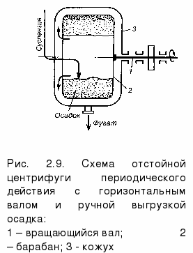
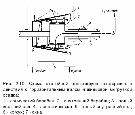
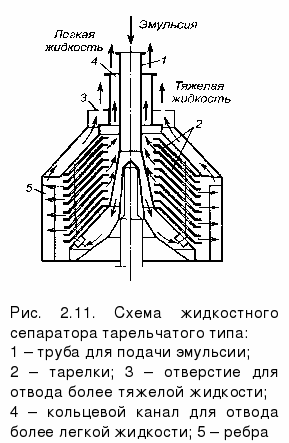
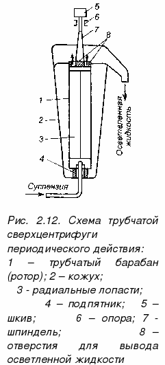
Apparatus for separating heterogeneous systems under the influence of centrifugal forceThe deposition rate under the action of gravity is small and to increase it, the deposition processes are carried out in the field of centrifugal forces. To create a field of centrifugal forces, one of two methods is usually used: either provide rotational movement of the flow in a stationary apparatus, or the flow is directed into a rotating apparatus. In the first case, the process is carried out in cyclones, in the second - in sedimentation centrifuges. Centrifugal forces in a cyclone (Fig. 2.7) are created due to the tangential gas supply to the cylindrical body of apparatus 1. Thanks to this gas injection, it acquires rotational motion around a pipe located along the apparatus axis and designed to discharge purified gas. Dust particles under the action of centrifugal force are thrown to the walls of the housing 1 and enter the discharge hopper 3. The smaller the radius of the cyclone, the greater the acceleration of the centrifugal force and the higher the separation factors. However, a decrease in the radius of the cyclone leads to an increase in flow velocity and an increase in hydraulic resistance. Therefore, at high costs of dusty gas, instead of one cyclone of large diameter, several smaller cyclone elements are installed, combined in one housing and working in parallel. Such devices are called battery cyclones(Fig. 2.8). 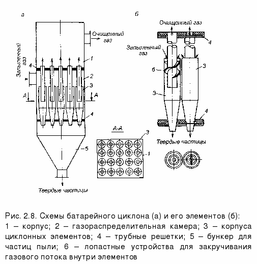 Since it is difficult to provide a tangential supply of dusty gas to each element of the cyclone, another principle of creating swirling flows is used - the installation of fixed blades on the inner tubes of the cyclones. For the deposition of solid particles from a liquid in a field of centrifugal forces hydrocycloneswhich differ from ordinary cyclones in the proportions of the individual parts and parts. Large centrifugal forces and high separation factors can be achieved in sedimentation centrifuges. In fig. 2.9 shows a diagram batch centrifuge. The main part of the centrifuge is a solid drum 2, mounted on a rotating shaft 1. Under the action of centrifugal force, solid particles from the suspension are thrown to the walls of the drum, forming a layer of sediment. The clarified liquid (centrate) is poured into a stationary body 3 (casing) and is removed through a pipe in its lower part. At the end of the sedimentation, the centrifuge is stopped and the sediment is unloaded manually. In fig. 2.10 shown continuous settling centrifuge with horizontal shaft and auger discharge. The suspension enters the inner drum through a pipe and is thrown through the windows into a conical rotating settling drum, where it is separated by centrifugal force. The clarified liquid (centrate) rushes into the wide part of the drum, flows into the fixed casing and is removed from it through the pipe. Sediment settles on the walls of the drum and moves with the screw, due to a small difference in the rotational speeds of the drum and the screw. Sludge centrifuges for emulsion separation are often referred to as separators. Continuous-plate separators are widespread (Fig. 2.11). The emulsion through the central tube enters the lower part of the rotating drum (rotor), equipped with a package of conical partitions - plates with holes. Passing through the hole, the emulsion is distributed in thin layers between the plates. During separation, the heavier liquid is discarded by centrifugal force to the wall of the drum, moves along it and is removed through the hole. The lighter fluid moves to the center of the drum and is removed through the annular channel. The fluid path is shown by arrows. The rotation speed of the drum is 5000 - 7000 rpm. If the fine suspension is separated, then separators with plates without holes are used. The solid dispersed phase of the suspension is deposited on the surface of each plate (except for the upper one), slides off them and accumulates near the wall of the drum. The clarified liquid moves to the center of the drum, rises up and leaves it. Sludge is discharged manually or automatically. Dish separators are characterized by high performance and high quality separation. Centrifuges with a very large number of revolutions (up to 60 thousand rpm) and large separation factors (over 3500) are called ultracentrifuges or supercentrifuges. The enormous centrifugal forces that arise in them are used to separate finely dispersed suspensions and emulsions. In order to achieve large separation factors, supercentrifuges have a small radius. In a tubular supercentrifuge of periodic action (Fig. 2.12), the suspension flows through the pipe into the rapidly rotating drum 1, enclosed in a casing 2. Inside the tubular drum (rotor) with continuous walls there are radial blades 3, which prevent the liquid from lagging behind the walls of the drum during its rotation. Solid particles of the suspension settle on the walls of the drum, and clarified liquid is ejected from it through the holes at the top 8 and is removed from the upper part of the casing. The precipitate is manually removed periodically after stopping the centrifuge and disassembling the drum. Such centrifuges are used only for separation of a suspension with a small solids content (not more than 1%). To separate the emulsion, tubular supercentrifuges of continuous action are used, which are distinguished by a more complex device in the upper part of the rotor, which allows separate separation of stratified liquids.
44. Devices in which absorption processes are carried out are called absorbers. Like other mass transfer processes, absorption occurs at the phase boundary. Therefore, the absorbers must have a developed contact surface between the liquid and gas. According to the method of formation of this surface, the absorbers can be divided into the following groups : superficial and film, nozzle, bubbling(dish-shaped), spraying.
Surface and film absorbers
In absorbers of this type, the contact surface of the phases is a mirror of a stationary or slowly moving liquid, or the surface of a flowing liquid film.
Surface absorbers. These absorbers are used to absorb readily soluble gases (for example, to absorb hydrogen chloride in water). In these apparatuses, gas passes over the surface of a stationary or slowly moving liquid (Fig. XI-6). Since the contact surface in such absorbers is small, several series-connected devices are installed in which the gas and liquid move countercurrently to each other. In order for the liquid to be mixed by gravity on the absorbers, each subsequent apparatus along the liquid is positioned slightly lower than the previous one. To remove the heat generated during absorption, coils are installed in the apparatus, cooled by water or another cooling agent, or the absorbers are placed in a vessel with running water.
A more perfect apparatus of this type is an absorber, consisting of a series of horizontal pipes irrigated outside with water. The required fluid level in each element 1 of such an apparatus is maintained using threshold 2.
Plate absorber consists of two channel systems: along channels 1 of a large cross-section, gas and absorbent move countercurrently, along channels 2 of a smaller cross-section - a cooling agent (usually water). Lamellar absorbers are usually made of graphite, as it is chemically resistant and conducts heat well.
Surface absorbers are of limited use due to their low efficiency and bulkiness.
Film absorbers. These devices are more efficient and compact than surface absorbers. In film absorbers, the phase contact surface is the surface of the flowing liquid film. The following types of devices of this type are distinguished: 1) tubular absorbers; 2) absorbers with a plane-parallel or sheet nozzle; 3) absorbers with an upward movement of the liquid film.
Tube absorber similar in design to a vertical shell-and-tube heat exchanger. The absorbent enters the upper tube sheet 1, is distributed through the pipes 2 and flows down their inner surface in the form of a thin film. In devices with a large number of pipes, for more uniform supply and distribution of liquid through the pipes, special distribution devices are used. The gas moves through the pipes from the bottom up towards the flowing liquid film. To remove the heat of absorption, water or another cooling agent is passed through the annulus.
Absorber with a plane-parallel nozzle. This apparatus is a column with a sheet nozzle 1 in the form of vertical sheets of various materials (metal, plastics, etc.) or tightly stretched cloth panels. In the upper part of the absorber there are distribution devices 2 for uniformly wetting the sheet nozzle on both sides.
Upstream absorber consists of pipes 1 fixed in tube sheets 2. Gas from chamber 3 passes through nozzles 4 located coaxially with pipes 1. Absorbent enters the pipes through slots 5. Gas moving at a sufficiently high speed carries the liquid film in the direction of its movement (from bottom to top) ), i.e. the device operates in an upward flow mode. At the outlet of the pipes 1, the liquid is drained onto the upper tube sheet and discharged from the absorber. To remove heat of absorption, a cooling agent is passed through the annulus. To increase the degree of extraction, absorbers of this type are used, consisting of two or more stages, each of which works according to the principle of direct flow, while in the apparatus as a whole, gas and liquid move countercurrent to each other. In apparatuses with an upward movement of the film due to high gas flow velocities (up to 30-40 m / s), high values \u200b\u200bof mass transfer coefficients are achieved, but at the same time, the hydraulic resistance of these apparatuses is relatively high.
Packed absorbers
Columns filled with packing — solid bodies of various shapes — were widely used in industry as absorbers. In the packed column (Fig. 7), the nozzle 1 is placed on the support lattices 2 having openings or slots for the passage of gas and liquid drain. The latter using the distributor 3 evenly irrigates the nozzle body and flows down. Over the entire height of the nozzle layer, a uniform distribution of liquid over the cross section of the column is usually not achieved, which is explained by the near-wall effect — a higher packing density in the central part of the column than at its walls. As a result, the liquid tends to spread from the central part of the column to its walls. Therefore, to improve the wetting of the nozzle in columns of large diameter, the nozzle is sometimes laid in layers (sections) of 2-3 m in height and under each section, except for the bottom, liquid redistributors 4 are installed.
In the packed column, the liquid flows through the packing element mainly in the form of a thin film, therefore the phase contact surface is mainly the wetted surface of the packing, and packing machines can be considered as a kind of film. However, in the latter, the film-like flow of liquid occurs along the entire height of the apparatus, and in packed absorbers, only along the height of the nozzle element. When liquid flows from one nozzle element to another, the liquid film is destroyed and a new film is formed on the underlying element. In this case, part of the liquid passes through the lower layers of the nozzle in the form of streams, drops and spray. Part of the surface of the nozzle is moistened with a stationary (stagnant) liquid.
The main characteristics of the nozzle is its specific surface a (m 2 / m 3) and free volume e (m 3 / m 3). The free volume for a non-porous nozzle is usually determined by filling the nozzle with water. The ratio of the volume of water to the volume occupied by the nozzle gives the value e. The equivalent nozzle diameter is found by the formula
Hydrodynamic modes.Packed absorbers can operate in various hydrodynamic modes.
The first mode –– film–– It is observed at low irrigation densities and low gas velocities. The amount of fluid retained in the nozzle in this mode is practically independent of the gas velocity.
The second mode –– suspension mode.In countercurrent phases due to an increase in the forces of friction of a gas against a liquid, a liquid is decelerated by the gas flow on the contact surface of the phases. As a result, the fluid flow rate decreases, and the thickness of its film and the amount of fluid held in the nozzle increase. In the suspension mode, as the gas velocity increases, the moistened surface of the nozzle increases and, accordingly, the intensity of the mass transfer process. In the suspension mode, the quiet flow of the film is disturbed: turbulences, splashes, i.e. conditions for the transition to sparging are created. All this contributes to an increase in the intensity of mass transfer.
The third mode –– emulsification mode–– arises as a result of fluid accumulation in the free volume of the nozzle. The accumulation of fluid occurs until the frictional force between the flowing fluid and the gas rising in the column balances the gravity of the fluid in the nozzle. In this case, conversion occurs or inversionphases (the liquid becomes a continuous phase, and the gas becomes a dispersed phase). A gas-liquid disperse system is formed, which in appearance resembles a bubbling layer (foam) or a gas-liquid emulsion. The emulsification regime begins in the narrowest section of the nozzle, the filling density of which, as indicated, is uneven over the cross section of the column. By carefully controlling the gas supply, the emulsification mode can be set along the entire height of the nozzle. The hydraulic resistance of the column increases sharply.
The emulsification mode corresponds to the maximum efficiency of the packed columns, primarily due to the increase in the phase contact surface, which in this case is determined not only (and not so much) by the geometric surface of the nozzle, but by the surface of the bubbles and jets of gas in the liquid filling the entire free volume of the nozzle. However, when the column is operating in this mode, its hydraulic resistance is relatively large.
In the modes of suspension and emulsification it is advisable to work if the increase in hydraulic resistance is not significant (for example, in the absorption processes carried out at elevated pressures). For absorbers operating at atmospheric pressure, the hydraulic resistance value may turn out to be unacceptably large, which will necessitate working in a film mode. Therefore, the most effective hydrodynamic regime in each case can be established only by technical and economic calculation.
In conventional packed columns, maintaining an emulsification regime is very difficult. There is a special design of flooded nozzle columns called emulsification (Fig. XI-14). In column 1, the emulsification mode is set and maintained using a drain pipe made in the form of a hydraulic shutter 2. The height of the emulsion in the apparatus is controlled by valves 3. For a more uniform distribution of gas over the cross section of the column, it has a plate 4. Emulsification columns can only be considered as packed ones conditionally. In these columns, the mechanism of phase interaction approaches the bubbling.
The load limit of packed absorbers operating in film mode is the emulsification point, or inversion. In conventional packed columns, the film mode is unstable and immediately goes into choking. Therefore, this point is called flooding point packed columns. With increasing irrigation rate, the limiting gas velocity decreases. At the inversion point, the gas velocity also decreases with an increase in the viscosity of the liquid and a decrease in its density. At the same gas and liquid flow rates, the gas velocity corresponding to the inversion point is higher for a larger nozzle.
The fourth mode –– ablation modeor reverse movement of fluid carried out of the apparatus by a gas stream. This mode is not used in practice.
45. Consider the principles of calculation of recuperative heat exchangers, widely used in OVT systems.
The heat transfer equation in which the local difference (t W 1 -t W 2) is replaced by the average temperature difference for the entire heat transfer surface (average temperature difference)? T cf, is the main one in this calculation:
46. \u200b\u200bPipes. Fields of application and features of strength analysis.
Transportation of substancesThe pipe effectively separates the external environment from the internal, while allowing the latter to move. Pipes are used to transport various substances, including poisonous, aggressive, in various states of aggregation: solid phase (bulk), liquid phase (various kinds of liquids), gas phase (steam, gas). Pipes are also used for transporting documents - pneumatic mail. Technological needsPipes are also used to transmit pressure as an impulse for technological needs. Construction of buildings and structuresThe pavilion of the water intake assembly made using various types of pipes Pipes (as well as non-tubular profiles) are more economical than continuous load-bearing structures with the same load resistance. Round and shaped pipes are often used as structural elements, independent elements: composite rigid metal structures: beams, crossbars, supports, arrows, spans; metal frames of buildings, for example, for subsequent sheathing with sandwich panels; Foundation elements: bored piles, hollow piles, pile, columnar foundations, support fences, bridges; Decorative elements; Communications ProtectionPipes are used to protect electrical wires, both power and information, and to protect optical fiber.
|
|
|
|
Various media transported in thermal power plants are characterized by a pressure of from about 0.05 to 300 bar and a temperature of from 10 to 535 ° C, in some cases even up to 650 ° C. Concerning, pipe strength calculation must be carried out in strict accordance with established requirements. Before choosing a material - possibly with the involvement of appropriate experts, it should be decided which of the various areas of use should include the calculated element. Up to a temperature of 300 ° C, special steels can be used without a guarantee of heat-resistant properties and pipe strength calculations. Depending on the acceptance tests, the maximum working head is specified. At temperatures above 300 ° C, products with guaranteed heat-resistant properties according to DIN 17175 and 17177 are used. Strength analysis of pipes is a very important and crucial moment. Used steels can be divided into the following groups: Carbon St 35.8, St 54.8. Chromomolybdenum 15MoZ, 13CrMo44, 10CrMo910. Heat-resistant fine-grained structural steels 15CuMoNb5, иМоЫЬ5, 17МnМоV64, 20МпМо45. Vanadium-doped 14MoV63, X20CrMoV121. Typical uses for these metal groups are: Medium and low pressure pipelines for power plants of power supply systems and fresh steam. Cold intermediate and power systems of power plants. Fresh steam pipelines of medium industrial power plants at temperatures up to 525 ° С. For the needs of nuclear power plants. For power plants and power supply systems. Pipelines of fresh steam at temperatures above 560 ° C. In order to ensure the reliability and durability of the line, it is necessary to make a qualitative calculation of the strength of the pipes. This will avoid downtime, loss of time and money. Very often, the designer has to make a choice of two or three steels with different strength parameters and different cost. In this case, you should choose the metal that has the lowest cost and provides the established requirements for elasticity and permissible rate of change of temperature. Within the calculation of the strength of pipes and other above-mentioned typical areas of research, steel should always be preferred with higher heat-resistant properties, both technically and economically. An exception may be intermediate pipelines of power plants of power supply systems, which for technical reasons should not be too thin-walled. Otherwise, it is difficult to perform hot bending within the required ovality. Corrosion phenomena are not observed in steam and condensate pipelines subject to the relevant operating instructions, therefore such systems do not have an internal protective coating. External painting is also not required if they have a heat-insulating layer. Pipelines for cooling water transport a liquid saturated with oxygen or containing an increased amount of salts, so they are coated on the inside with either paint or another protective layer. If they are laid in the ground, external protection is still required. Products that conduct air-vapor mixture, such as pipelines of degassing plants that transport wet steam, are also subject to increased corrosion. In this case, austenitic stainless and acid-resistant steels or products with a galvanized surface, requiring preliminary calculation of pipe strength, are used. |
47. The main heat-exchange element is a coil - a pipe bent
on a specific profile.
The coil is immersed in the fluid located in the apparatus.
The speed of movement is small due to the large cross section of the apparatus body, which
causes low values \u200b\u200bof heat transfer coefficients from the outdoor
the wall of the coil to the liquid (or vice versa). To increase this
heat transfer coefficients increase the fluid velocity by
installation in the apparatus, inside the coil, cup. In this case
the fluid moves along the annular space between the walls of the apparatus and
glasses with increased speed. Often in immersion heat exchangers
install coils from straight pipes connected by kalach.
Due to the simplicity of the device, low cost, availability,
external walls of the coil for cleaning and inspection, work options
at high pressures, these heat exchangers find enough
widespread use in industry. Submersible coil
heat exchangers have a relatively small heat exchange surface (up to
SUBMERSIBLE COIL HEAT EXCHANGERS are used in
chemical industry for heat transfer between media, one of
which is under high pressure. These heat exchangers consist of
flat or cylindrical coils immersed in a vessel with liquid
working environment. Other liquid or gaseous pressure medium
passed through pipes.
Coil cooler (fig. 13) designed for cooling
nitrogen-nitrogen mixture, consists of four annular sections 1, included
parallel to the flow of gas and water. To the outer and inner shells of the casing
5 of each section, collectors 3 are mounted for supply and output from sections
cooling water. Section manifolds are offset from one another
90 °. Gas is supplied to each section from the top along the vertical manifold
2 and is distributed among 14 planar spiral coils 4 welded to it, 4,
located one above the other. The cooled gas mixture is discharged by
the same collector in the inner shell of the casing. Between the coils
29 a spiral sheet steel wall is installed that communicates with water
the direction of movement in a spiral along the turns of the coils is countercurrent to the gas.
Figure 13 Coil cooler
These heat exchangers are characterized by good ability to
self-compensation of temperature stress and low hydraulic
resistance. Their disadvantage is the complexity of manufacturing and installation.
48. a catalytic process is a combination of ordinary chemical reactions (in solution, on a surface or in a gas), but a combination is special, having a cyclic nature.
Under the conditions of the catalytic processes are homogeneous (the reaction proceeds in the volume of the solution or in the volume of the gas phase) and heterogeneous (the reaction occurs on the surface of a solid). In the presence of two phases (liquid-liquid, liquid-solid), catalysts are also used - carriers of reagents from one phase to another (interfacial catalysis). Moreover, interfacial transfer catalysts perform not only the physical (transport) function, but also significantly affect the reactivity of the transferred particle.
49. Crystallization is the process of the phase transition of a substance from a liquid state to a solid crystalline state with the formation of crystals. Phase is the homogeneous part of the thermodynamic system separated from other parts of the system (other phases) by the interface, upon transition through which the chemical composition, structure and properties of the substance change in jumps.
Crystallization is the process of isolating a solid phase in the form of crystals from solutions or melts; in the chemical industry, the crystallization process is used to obtain substances in pure form.
Crystallization begins when a certain limiting condition is reached, for example, supercooling of a liquid or supersaturation of a vapor, when many small crystals appear almost instantly - crystallization centers. Crystals grow by attaching atoms or molecules from a liquid or vapor. The growth of crystal faces occurs in layers, the edges of incomplete atomic layers (steps) during growth move along the face. The dependence of the growth rate on crystallization conditions leads to a variety of growth forms and crystal structures (polyhedral, lamellar, needle, skeletal, dendritic and other forms, pencil structures, etc.). In the process of crystallization, various defects inevitably arise.
The number of crystallization centers and the growth rate are significantly affected by the degree of supercooling.
The degree of supercooling is the level of cooling of a liquid metal below the temperature of its transition to crystalline (solid) modification. S.p. necessary to compensate for the energy of latent heat of crystallization. Primary crystallization is the formation of crystals in metals (alloys and liquids) during the transition from a liquid to a solid state.
50. In homogeneous systems, all reacting substances are in one single phase: gas (g), liquid (g) or solid (t). In heterogeneous systems, reacting substances are in different phases, gas-liquid (g - g), gas-solid (g - t), liquid-solid (g - t), two immiscible liquids (g - g) and two solid phases ( t - t). The most common systems in industrial processes are g - g, g - t, and g - t. Sometimes three or four phases are involved in industrial processes, for example, g - g - t, g - g - g, g - g - t - t Usually, only the main components are taken as separate phases and do not take into account the presence of small amounts of impurities. So, for example, the g - g and g - t systems often contain a gas phase, because the processes are carried out in the presence of air or other gases, or in the presence of vapors, since the liquid components partially evaporate. But the gas phase is taken into account only if it has a significant impact on the process. Some processes begin in a homogeneous environment, and then, as a result of the appearance of a new phase, the system becomes heterogeneous. For example, upon receipt of polystyrene, benzoyl peroxide is added to liquid styrene and heated, while styrene polymerizes to form a new phase - solid polystyrene. The reaction rate in homogeneous systems is higher than in heterogeneous systems, since in the first case the reactions proceed at the level of individual molecules (the so-called microlevel). Therefore, in practical conditions, it is usually sought to convert a heterogeneous process into a homogeneous process (by melting or dissolving solid reactive substances, absorption or condensation of gases). The phase contact surface can be increased mainly due to the corresponding hardware design of the process, i.e. by using reactors of various design. For example, in the Ms. system, the process is often carried out in nozzle towers or in hollow towers. In the first case, the nozzle is irrigated with a liquid, which, flowing down, moistens the nozzle (Fig. 4.8). The gas passes through the nozzle and is in contact with the liquid wetting the nozzle. Liquid surface i.e. the phase contact surface (F), the larger the larger the nozzle volume per unit volume of the transmitted gas, the smaller the nozzle size and the more developed the surface of this nozzle. In some cases in G-systems, the process is carried out in bubblers and foam apparatuses, in which gas in the form of separate bubbles sparges through a liquid layer. The contact surface is the inner surface of the bubbles: the smaller the size of the gas bubbles and the higher the liquid layer, the larger the surface F. For the g - t system, an increase in the contact surface of the phases is achieved by grinding the solid phase. The gaseous substance is brought into contact with the crushed starting material in a variety of ways, for example, solid particles of the substance are placed on the shelves of the reactor, and the gas flow moves over the shelves. In other cases, the finely divided solid starting material is sprayed into the gaseous starting material stream in a hollow volume; thus, pulverized fuel is burned in the furnaces of steam boilers. In reactors with a fluidized (fluidized) bed, the contact surface of the phases is greater, the finer the particles of granular material and the higher the layer of this material.
Shell-and-tube heat exchangers are designed for heating, cooling, condensation and evaporation of liquid, gas, steam and their mixtures in the oil, oil refining, petrochemical, chemical, gas and other industries.
According to the method of heat transfer, heat exchangers are subdivided into surface ones where there is no direct contact of heat carriers, and heat transfer occurs through a solid wall, and mixing ones, where heat carriers contact directly. Surface heat exchangers, in turn, are divided into regenerative and regenerative, depending on the simultaneous or alternating contact of the coolants with the wall separating them
Structurally, heat exchangers are divided into:
voluminous one of the media has a significant volume in the heat exchanger, one medium is concentrated in a large tank, the second flows through the coil;
high-speed (shell-and-tube) media move at a sufficiently high speed to increase the heat transfer coefficient, many small tubes are located in one large tube (shell), the media move alone in the annulus, the other inside the tubes, usually the tubes have a more “dirty” environment, since they are lighter clean;
plate heat exchanger consists of a set of plates, media move between the plates, easy to manufacture (stamped plates stack with gaskets between them), easy to modify (plates are added or removed), good efficiency (large contact area through the plates).
plate fin heat exchanger unlike a plate heat exchanger, it consists of a system of dividing plates, between which there are ribbed surfaces - nozzles attached to the plates by vacuum soldering.
Finned Plate Heat Exchangers, WHOLESALE consists of thin-walled finned panels made by high-frequency welding, connected alternately with a rotation of 90 degrees. Due to the design, as well as the variety of materials used, high temperatures of heating media, low resistances, high ratios of the tele-transmitting area to the mass of the heat exchanger, long service life, low cost, etc. are often achieved. They are often used to recover the heat of the exhaust gases.
spiral heat exchanger represents two spiral channels, wound from a rolled material around a central dividing wall - core, the medium moves along the channels. One of the purposes of spiral heat exchangers is the heating and cooling of highly viscous fluids.
Advantages and disadvantages Shell-and-tube heat exchangers are characterized by resistance to water hammer, reduced requirements for clean media, relatively low heat transfer coefficient and, as a result, large dimensions and areas required for maintenance, as well as high price due to the high metal consumption. In addition, repair of such heat exchangers is usually associated with plugging damaged pipes, which leads to a decrease in heat transfer area. Therefore, heat exchangers are usually selected with a large reserve on the surface, which also determines their large dimensions. An attempt to control condensate on horizontal shell and tube heat exchangers is difficult. This is due to the fact that with a slight change in the level of condensate, the heat transfer area changes nonlinearly and is much more significant. Nevertheless, modern shell-and-tube heat exchangers are close to plate and shell-plate heat exchangers in terms of efficiency, heat transfer coefficient and dimensions. This is achieved through the use of so-called flow turbulizers - baffles in the tubes and the annular space, as well as corrugated tubes in which the medium flow is highly turbulized, which leads to an increase in the heat transfer coefficient, and, as a result, to a decrease in dimensions. Recently, vertical shell and tube heat exchangers have been used to reduce the use of production space. They allow you to organize condensate control, if necessary.
52. Method of strengthening holes
In shells, bottoms, and some other parts of chemical apparatuses, it is often required to have various kinds of openings: for fittings, pipe inlets, manholes, manholes, etc. Such openings weaken the corresponding wall of the apparatus and therefore in many cases (especially with large diameters holes) require reinforcement. Distinguish holes unreinforced and reinforced. Unsecured are openings for flaring pipes, for threads, as well as openings sealed with any closures. The holes may be partially reinforced.
Temperature stresses in rigid heat exchangers occur at different temperatures of the pipes and the casing, as well as when their temperature is the same, but the pipes and the casing are made of different materials, the elongation coefficients of which are very different.
In pipes and in casings, temperature stresses are aT \u003d Q / F.
It is desirable that the temperature stresses in the tubes and the casing are not more than 0.5 [a].
If the stresses are excessively large, additional lenses must be installed to reduce axial force.
For example, during the start-up period, temperature stresses can occur that are much higher than during normal operation.
Some critical devices even develop a special starting temperature mode to prevent excessive temperature stresses during start-up.
In heat exchangers with a floating head and with U-shaped tubes, temperature stresses are absent.
In multi-pass heat exchangers with a significant difference in the temperature of the coolant, temperature stresses are also possible due to the temperature difference of the pipes at different points of the tube bundle.
It is impossible to compensate for these voltages.
In a rigid shell-and-tube heat exchanger, tensile stresses always arise due to pressure both in the tubes and in the casing
Flange - This is a method of connecting pipes, valves, pumps and other equipment to form a piping system. This connection method provides easy access for cleaning, inspection or modification. Flanges are usually threaded or welded. The flange connection consists of two flanges fixed with bolts and gaskets between them, to ensure tightness.
Pipe flanges are made of various materials. The flanges have machined surfaces and are made of cast iron and nodular cast iron, but the most used material is forged carbon steel.
The most used flanges in the oil and chemical industries:
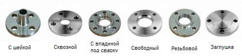
Special flanges
With the exception of the flanges mentioned above, there are a number of special flanges, such as:
An example of a welded flange with a shoulder 6 "- 150 # -S40
Each flange complying with ASME B16.5 has a defined number of standard sizes. If a Japanese designer, or a person preparing a project for launch in Canada, or a pipeline installer in Australia, speaks of a 6 "-150 # -S40 welded flange that meets ASME B16.5, then he means the flange that is shown below. 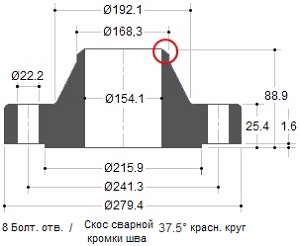
When ordering a flange, the supplier would like to know the quality of the material. For example, ASTM A105 is a stamped carbon steel flange, while A182 is a stamped alloy steel flange. Thus, according to the rules, both standards must be specified for the supplier: Welded flange 6 "-150 # -S40-ASME B16.5 / ASTM A105.
PRESS CLASS
The pressure class or classification for flanges will be presented in pounds. Different names are used to indicate the pressure class. For example: 150 Lb or 150Lbs or 150 # or Class 150, mean the same thing.
Forged steel flanges have 7 main classifications:
150 Lbs - 300 lbs - 400 lbs - 600 lbs - 900 Lbs - 1500 lbs - 2500 lbs
The concept of flange classification is clear and obvious. A class 300 flange can operate at higher pressures than a class 150 flange because the class 300 flange has more metal and can withstand more pressure. However, there are a number of factors that can affect the flange pressure limit.
EXAMPLE
Flanges can withstand various pressures at different temperatures. With increasing temperature, the pressure class of the flange decreases. For example, a Class 150 flange is designed for pressures of approximately 270 PSIG at ambient conditions, 180 PSIG at 200 ° C, 150 PSIG at 315 ° C, and 75 PSIG at 426 ° C.
Additional factors are that the flanges can be made of various materials, such as alloy steel, cast and malleable cast iron, etc. Each material has different pressure classes.
PARAMETER "PRESSURE-TEMPERATURE"
The pressure-temperature class determines the working, maximum permissible overpressure in bars at a temperature in degrees Celsius. For intermediate temperatures linear interpolation is allowed. Interpolation between the designation class is not allowed.
Pressure-Pressure Classifications
The Temperature-Pressure class is applicable to flange connections that comply with the restrictions on bolted connections and gaskets that are made in accordance with good practice for assembly and alignment. The use of these classes for flange connections that do not meet these restrictions is the responsibility of the user.
The temperature shown for the corresponding pressure class is the temperature of the inner shell of the part. Basically, this temperature is the same as the contained liquid. In accordance with the requirements of current codes and rules, when using a pressure class corresponding to a temperature different from the flowing liquid, all responsibility lies with the customer. For any temperature below -29 ° C, the grade should not be higher than when used at -29 ° C.
As an example, below you will find two tables with groups of materials in accordance with ASTM and two other tables with class temperature-pressure for these materials in accordance with ASME B16.5.
| ASTM Group 2-1.1 Materials |
|||
| Reference designation |
Stamping |
Casting |
Plates |
| C-si | A105 (1) | A216 Gr.WCB (1) |
A515 Gr.70 (1) |
| C-Mn-Si | A350 Gr.LF2 (1) | - | A516 Gr.70 (1), (2) |
| C-Mn-Si-V | A350 Gr.LF6 Cl 1 (3) | - | A537 Cl. 1 (4) |
| 3½Ni |
A350 Gr.LF3 |
- | - |
NOTES:
|
|||
| Temperature-Pressure Class for ASTM Group 2-1.1 Materials Working pressure by grade |
|||||||
| Temperature ° C | 150 | 300 |
400 |
600 |
900 |
1500 |
2500 |
| from 29 to 38 |
19.6 | 51.1 | 68.1 | 102.1 | 153.2 | 255.3 | 425.5 |
| 50 | 19.2 | 50.1 | 66.8 | 100.2 | 150.4 | 250.6 | 417.7 |
| 100 | 17.7 | 46.6 | 62.1 | 93.2 | 139.8 | 233 | 388.3 |
| 150 | 15.8 | 45.1 | 60.1 | 90.2 | 135.2 | 225.4 | 375.6 |
| 200 | 13.8 | 43.8 | 58.4 | 87.6 | 131.4 | 219 | 365 |
| 250 | 12.1 | 41.9 | 55.9 | 83.9 | 125.8 | 209.7 | 349.5 |
| 300 | 10.2 | 39.8 | 53.1 | 79.6 | 119.5 | 199.1 | 331.8 |
| 325 | 9.3 | 38.7 | 51.6 | 77.4 | 116.1 | 193.6 | 322.6 |
| 350 | 8.4 | 37.6 | 50.1 | 75.1 | 112.7 | 187.8 | 313 |
| 375 | 7.4 | 36.4 | 48.5 | 72.7 | 109.1 | 181.8 | 303.1 |
| 400 | 6.5 | 34.7 | 46.3 | 69.4 | 104.2 | 173.6 | 289.3 |
| 425 | 5.5 | 28.8 | 38.4 | 57.5 | 86.3 | 143.8 | 239.7 |
| 450 | 4.6 | 23 | 30.7 | 46 | 69 | 115 | 191.7 |
| 475 | 3.7 | 17.4 | 23.2 | 34.9 | 52.3 | 87.2 | 145.3 |
| 500 | 2.8 | 11.8 | 15.7 | 23.5 | 35.3 | 58.8 | 97.9 |
| 538 | 1.4 | 5.9 | 7.9 | 11.8 | 17.7 | 29.5 | 49.2 |
| Temperature-Pressure Class for ASTM Group 2-2.3 Materials Working pressure by grade |
|||||||
| Temperature ° C | 150 | 300 |
400 |
600 |
900 |
1500 |
2500 |
| from 29 to 38 |
15.9 |
41.4 |
55.2 |
82.7 |
124.1 |
206.8 |
344.7 |
| 50 | 15.3 |
40 |
53.4 |
80 |
120.1 |
200.1 |
333.5 |
| 100 | 13.3 |
34.8 |
46.4 |
69.6 |
104.4 |
173.9 |
289.9 |
| 150 | 12 |
31.4 |
41.9 |
62.8 |
94.2 |
157 |
261.6 |
| 200 | 11.2 |
29.2 |
38.9 |
58.3 |
87.5 |
145.8 |
243 |
| 250 | 10.5 |
27.5 |
36.6 |
54.9 |
82.4 |
137.3 |
228.9 |
| 300 | 10 |
26.1 |
34.8 |
52.1 |
78.2 |
130.3 |
217.2 |
| 325 | 9.3 |
25.5 |
34 |
51 |
76.4 |
127.4 |
212.3 |
| 350 | 8.4 |
25.1 |
33.4 |
50.1 |
75.2 |
125.4 |
208.9 |
| 375 | 7.4 |
24.8 |
33 |
49.5 |
74.3 |
123.8 |
206.3 |
| 400 | 6.5 |
24.3 |
32.4 |
48.6 |
72.9 |
121.5 |
202.5 |
| 425 | 5.5 |
23.9 |
31.8 |
47.7 |
71.6 |
119.3 |
198.8 |
| 450 | 4.6 |
23.4 |
31.2 |
46.8 |
70.2 | 117.1 |
195.1 |
The shape and design of the flange surface will determine where the o-ring or gasket is located.
Most used types:
Surface with protrusion, the most applicable type of flange that is easy to identify. This type is called so because the surface of the gasket protrudes above the surface of the bolted joint. 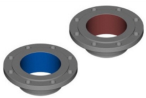
Diameter and height are determined according to ASME B16.5 using pressure class and diameter. In the pressure class up to 300 Lbs, the height is approximately 1.6 mm, and in the pressure class from 400 to 2500 Lbs the height is about 6.4 mm. The flange pressure class determines the height of the surface protrusion. The purpose of the (RF) flange is to concentrate more pressure on a smaller gasket area, thereby increasing the ultimate pressure of the joint.
For the parameters determining the height of all the flanges described in this article, the sizes H and B are used, with the exception of the lap with an overlap connection, this must be understood and remembered as follows:
In pressure classes 150 and 300 Lbs, the protrusion height is about 1.6 mm (1/16 inch). Almost all flange suppliers of these two classes indicate sizes H and B in their brochures or catalogs, including the projection surface (see Fig. 1 below) 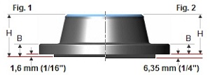
For pressure classes 400, 600, 900, 1,500, and 2,500 Lbs, the protrusion height is 6.4 mm (1/4 inch). In these classes, many suppliers indicate sizes H and B, not including the protrusion height (see Fig. 2 above)
In this article you will find two sizes. The top row of sizes does not include the height of the protrusion, and the dimensions in the bottom row include the height of the protrusion.
FLAT SURFACE (FF - Flat Face)
For a flange with a flat surface (entire surface), the gasket is in the same plane as the bolted joint. Most often, flanges with a flat surface are used where the counter flange or fitting is cast. 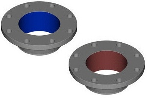
A flange with a flat surface never connects to a flange that has a protrusion. According to ASME B31.1, when connecting flat cast iron flanges to carbon steel flanges, the protrusion on the steel flange must be removed and the entire surface must be sealed with a gasket. This is to preserve the thin, brittle cast iron flange from cracking due to the protrusion of the steel flange.
RING SEAL FLANGE (RTJ - Ring Type Joint)
At the RTJ flanges, grooves are cut in their surface into which steel o-rings are inserted. The flanges are sealed due to the fact that when tightening the bolts, the gasket between the flanges is pressed into the grooves, deformed, creating a close contact - metal-K-metal. 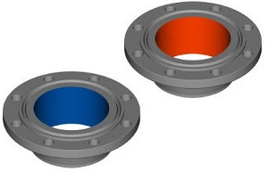
An RTJ flange may have a protrusion with an annular groove made therein. This protrusion does not serve as any seal. For RTJ flanges that are sealed with O-rings, the protruding surfaces of the connected and tightened flanges can be in contact with each other. In this case, the compressed gasket will no longer bear additional loads, tightening the bolts, vibration and displacements will no longer be able to crush the gasket and reduce the torque.
Metal O-rings are suitable for use at high temperatures and pressures. They are made taking into account the correct choice of material and profile and are always used in the corresponding flanges, providing a good and reliable seal.
O-rings are made so that the sealing is carried out by means of an “initial contact line” or jamming between the mating flange and the gasket. By applying pressure to the seal through bolt tightening, the softer gasket metal penetrates the finely dispersed structure of the stiffer flange material and creates a very dense and effective seal. 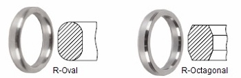
Most used rings:
Type R-Oval according to ASME B16.20
Suitable for ASME B16.5 flanges of pressure class from 150 to 2500.
Type R-Octagonal according to ASME 16.20
Improved design compared to the initial R-Oval. However, they can only be used for flat groove flanges. Suitable for ASME B16.5 flanges pressure class 15 to 2500.
SEAL AND SURFACE FLANGE TYPE PROJECT-DEPRESSION (LMF - Large Male Face; LFF - Large Female Face)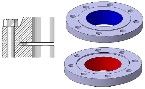
Flanges of this type must match. One flange surface has an area that extends beyond the normal limits of the flange surface ( dad) The other flange or counterflange has a corresponding recess ( mother) made in its surface.
Semi-free gasket
FLANGE WITH SEALING SURFACE TYPE SHIP-PAZ
(Lug - Tounge Face - TF; Trench - Groove Face - GF)
Flanges of this type must also match. One flange has a ring with a protrusion (spike) made on the surface of this flange, while a groove is grooved on the surface of the reciprocal. Such surfaces are commonly found on pump caps and valve covers.
Fixed gasket
FLAT SURFACE AND groove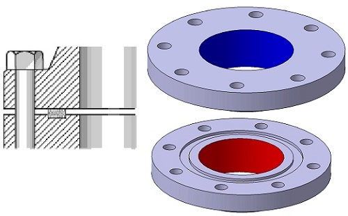
Fixed gasket
FINISHING THE FLANGE SURFACE
According to ASME B16.5 code, the flange surface (protrusion and flat surface) must have a certain roughness, so that this surface, when combined with the gasket, provides a high-quality seal. 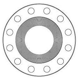
The final corrugation, concentric or in the form of a spiral, requires from 30 to 55 grooves per inch, which results in a roughness between 125 and 500 micro-inches. This will allow manufacturers of flanges to do the processing of a place for laying a metal flange of any class.
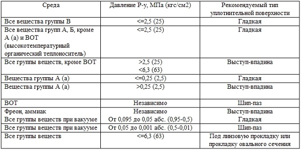
For pipelines transporting substances of groups A and B of technological objects of explosion hazard category I, it is not allowed to use flange connections with a smooth sealing surface, except for the cases of using spiral wound gaskets.
MOST USED SURFACES
Roughing
| Most commonly used when machining any flange, because it is suitable for almost all normal operating conditions. When compressed, the soft surface of the gasket will enter the machined surface, which will help create a seal, in addition, a high level of friction occurs between the connected parts. Finishing for these flanges is done using a radius cutter with a radius of 1.6 mm at a feed speed of 0.88 mm per revolution for 12 ". For 14" or more, processing is done using a 3.2 mm radius cutter with a feed of 1.2 mm per revolution. |
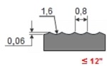 |
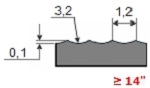 |
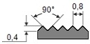 This can be a continuous or phonographic spiral groove, but it differs from roughing in that the groove is obtained through the use of a 90 degree cutter, which creates a V-shaped profile with a 45 ° groove angle.
 Concentric notch.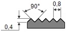 As the name implies, machining consists of concentric grooves. A 90 ° cutter is used and the rings are distributed evenly over the entire surface.
Smooth surface.![]() Such processing does not visually leave traces of the tool. Such surfaces, as a rule, are used for gaskets with a metal surface, for example: with a double shell, made of strip steel, or corrugated metal. A smooth surface helps create a seal and depends on the flatness of the opposite surface. As a rule, this is achieved due to the contact surface of the gasket formed by a continuous (sometimes called phonographic) spiral groove made by a 0.8 mm radius cutter at a feed of 0.3 mm per revolution, 0.05 mm deep. This will result in a roughness between Ra 3.2 and 6.3 micrometers (125-250 micro-inches)
Such processing does not visually leave traces of the tool. Such surfaces, as a rule, are used for gaskets with a metal surface, for example: with a double shell, made of strip steel, or corrugated metal. A smooth surface helps create a seal and depends on the flatness of the opposite surface. As a rule, this is achieved due to the contact surface of the gasket formed by a continuous (sometimes called phonographic) spiral groove made by a 0.8 mm radius cutter at a feed of 0.3 mm per revolution, 0.05 mm deep. This will result in a roughness between Ra 3.2 and 6.3 micrometers (125-250 micro-inches)
GASKETS
In order to make a tight flange connection, gaskets are needed. 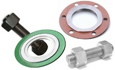
A gasket is compressed sheets or rings used to create a waterproof joint between two surfaces. Gaskets are made to work at extreme temperatures and pressures, and are available in metal, semi-metallic and non-metallic materials.
For example, the principle of sealing can consist in compressing the gasket between two flanges. The gasket fills the microscopic spaces and surface irregularities of the flanges and then forms a seal that prevents leakage of liquids and gases. Correct and careful installation of the gasket is required in order to prevent leaks in the flange connection.
This article will describe the gaskets corresponding to ASME B16.20 (Metal and semi-metal gaskets for pipe flanges) and ASME B16.21 (Non-metal, flat gaskets for pipe flanges)
BOLTS
Bolts are needed to connect the two flanges to each other. The number will be determined by the number of holes in the flange, and the diameter and length of the bolts depends on the type of flange and its pressure class. The most commonly used bolts in the oil and chemical industries for ASME B16.5 flanges are studs. The stud consists of a threaded rod and two nuts. Another type of bolt available is a regular hex bolt and one nut bolt.
Sizes, dimensional tolerances, etc. were defined in ASME B16.5 and ASME B18.2.2, materials in various ASTM standards.
TORQUE
In order to get a tight flange connection, the correct installation of the gasket is necessary, the bolts must have the required tightening torque, and the total tension from the tightening must be evenly distributed throughout the flange. 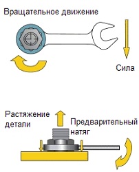
The necessary stretching is carried out due to the tightening torque (application of the preload to the fastening due to the rotation of its nut).
The correct tightening torque of the bolt allows the best use of its elastic properties. To perform its task well, the bolt must behave like a spring. During operation, the tightening process exerts an axial, preliminary load on the bolt. Of course, this tensile force is equal to the opposite compressive forces applied to the components of the assembly. It may be called a tensile force or tensile force.
DYNAMETRIC KEY
A torque wrench is the generic name for a hand tool, which is used to apply the exact tightening force of joints, whether it be a bolt or a nut. This allows the operator to measure the rotational force (torque) applied to the bolt, which must match the specification. 
Choosing the right technique to tighten the flange bolt requires experience. The correct application of any of the techniques also requires qualifications, both of the tool that will be used and of the specialist who will perform the work. The following are the most commonly used methods for tightening bolts:
The key to reducing these effects is the correct installation of the gasket. When installing the gasket, it is necessary to combine the flanges together and smoothly and parallelly, with the least tightening torque, tighten the 4 bolts following the correct tightening sequence. This will reduce operating costs and increase safety.
The correct thickness of the gasket is also important. The thicker the gasket, the higher its creep, which, in turn, can lead to a loss of tightening torque. According to ASME, for flanges with a corrugated surface, a 1.6 mm thick gasket is generally recommended. Thinner materials can work at higher gasket loads and, therefore, higher internal pressures.
LUBRICATION REDUCES FRICTION
Lubrication reduces friction during tightening, reduces bolt disruption during installation, and increases service life. A change in the coefficient of friction affects the amount of preload achieved at a specific tightening torque. A higher coefficient of friction leads to less conversion of torque to preload. The value of the coefficient of friction provided by the lubricant manufacturer must be known in order to accurately establish the required torque value.
Grease or anti-seize joints must be applied both to the surface of the bearing nut and to the external thread.
PUSH SEQUENCE The first pass, slightly tighten the first bolt, then the next one opposite it, then a quarter turn in a circle (or 90 degrees) to tighten the third bolt and, opposite it, the fourth. Continue this sequence until all bolts are tightened. When tightening flanges with four bolts, use a cross pattern.
PREPARATION FOR FIXING THE FLANGE
To achieve tightness in flanged joints, all components must be accurate.
Before starting the connection process, the following steps must be taken to avoid future problems:
From internal pipelines, drains are transported by external ...

Each apartment, like every family, has its own characteristics, so it is difficult ...