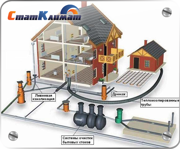
From internal pipelines, drains are transported by external ...

You can often hear that the “gasket is leaking”. This statement is not always true. In fact, the connection always leaks, and the gasket is only one of its components. It is often expected that the gasket is able to compensate for flaws in the working surfaces of the flanges and the displacement of the flanges as a result of changes in operating temperature and pressure, vibration, etc. In many cases, gaskets are capable of this, but only with the correct choice of their type and material, as well as subject to the correct installation procedure.
The joints should be tightened evenly in three or even four passes, in a criss-cross sequence, as shown in the figure. Keep in mind that in this sequence, tightening one of the bolts can lead to the weakening of the other (others), therefore, as a last step, additional tightening of all bolts in a circle is recommended. Some connections must be retightened immediately before commissioning in order to compensate for the relaxation of gaskets and fasteners. Also, in some cases, when using gaskets of certain types together with flanges of some forms of the connecting surface on heat exchangers, it is necessary to carry out an additional tightening of the connection during initial heating of the heat exchanger.
| MALFUNCTION | POSSIBLE REASON | SOLUTION METHOD |
| Leak occurred immediately when the medium was supplied to the pipeline | Inadequate or excessive load in the connection or load applied unevenly | Carefully insert a new gasket. Check the alignment of the flanges, their working surfaces and tighten the bolts in accordance with the procedure described. |
| Leak occurs after a short operation |
|
|
| Leak occurs after several hours or days of operation | Chemical effect on the gasket from the medium or its mechanical destruction. | Check the chemical compatibility of the gasket material with the medium at a given concentration under operating conditions. Check the correctness of the choice of gasket type. |
Assembly of flanged joints should be subject to the following basic requirements. Bolts and studs of pipelines operating at temperatures above 300 ° C must be programmed before installation. Gaskets should be sized to match the sealing surfaces of the flanges.
Assembly of flanged joints should be subject to the following basic requirements. Bolts and studs of pipelines operating at temperatures above 300 ° C must be programmed before installation. Gaskets should be sized to fit the flange surfaces.
Control plates for the sealing surfaces of flanges with protrusion and depression. Tightening flange bolts. Assembly of flanged joints is one of the most frequently performed and critical operations in the repair and installation of fittings. Only products for which the roughness and flatness of the sealing surfaces of the flanges comply with the established technical requirements are allowed to be assembled. Transverse risks crossing the annular sealing surface of the flange under the gasket, nicks and other defects are not allowed.
Assembly of flange joints should be carried out without adjustment operations; the bolts in the holes should enter freely, without voltage.
Assembly flange connection consists of installing gaskets and fastening flanges using fasteners.
Assembly of flange joints begins by putting flanges on the ends of the pipes, then the Simplex rubber rings are pulled and gaskets are installed between the ends of the pipes. Next, the rapprochement of the flanges begins and their tightening with bolts.
The assembly of flanged joints is one of the labor-intensive operations during the installation of air ducts, for the mechanization of which electric wrenches are used.
Mobile device for fitting flanges. An assembly of flange joints consists of a joint of flanges, installation of gaskets and tightening of bolts or studs. Before installation, bolts (studs) and pipelines operating at temperatures above 200 ° C must be programmed.
Assembling flanged joints is a critical operation in the manufacture of piping assemblies. In order to achieve a good density of the flange joints and to maintain it during operation, the flange joint must be correctly assembled and tightened.
Assembly of flanged joints is one of the most common and critical operations in the manufacture and installation of pipelines, since their decompression during operation necessitates the shutdown of the pipeline. The product passes through leaking flange joints due to weak tightening of the flanges, distortions between the flange planes, insufficient cleaning of the sealing surfaces before installation of the gasket, improper installation of the gasket, use of gasket material that does not meet the product parameters, defects on the sealing surfaces. The deviation from the perpendicularity of the flange to the axis of the pipe (skew), measured by the outer diameter of the flange, should not exceed 0 2 mm for every 100 mm of the diameter of the pipeline, designed to work under pressure up to 1 6 MPa, 0 1 mm - under pressure 1 6 - 6 4 MPa and 0 05 mm - under pressure above 6 4 MPa. Thus, the displacement should not exceed 1 mm with a hole diameter of 12 - 18 mm, 1 5 mm - with a diameter of 23 - 33 mm, 2 mm - with a diameter of 40 - 52 mm. When installing flat welded flanges, the pipe end must be recessed into the flange.
Adaptation KTB-1222 for flushing mirrors flanges. Flanged joints are assembled using a square or using the device shown in fig. VII-7. For joining pipes for welding, the devices shown in Fig. VII-8. For marking pipes at the place of installation, an ordinary compass can be used.
Assembly of flanged joints on bolts or studs should be carried out freely, without the use of fitting operations.
Assembling flanged joints of plastic pipelines consists in installing gaskets between the flanges and tightening the bolts with nuts. In case of mismatch of the ends of the pipes to be joined, they perform fitting work consisting of a piece of pipe piece and welding (gluing) of the shoulder sleeve or flanged pipe. Before welding the sleeve or pipe, a loose flange is put on the cut end of the pipe. The exception is fluoroplastic and faolitic pipelines, in which it is impossible to form a shoulder on the part in the conditions of the installation site. In this case, it is necessary to replace the entire part, this is done by installing straight pipe sections of the required length. If the ends of the glass pipes do not coincide, correction can only be done by cutting off an extra piece of pipe. If the pipe is shorter than necessary, the gap is eliminated with inserts of at least 200 mm in length for joints on flanges with two tension rings and at least 250 mm for joints on flanges with three tension rings.
The assembly of flanged joints of pipeline elements is carried out on exposed, calibrated and reinforced supports on which pipes, connecting parts or fittings are laid and pre-strengthened. Between the ends of the joined elements of the pipeline leaves a minimum gap through which it is possible to get the lens.
Assembly of flanged joints of high pressure pipelines is carried out in compliance with a number of additional requirements. Before assembly, the studs are rubbed with flake graphite or lubricated with a graphite paste composed of graphite, densely mixed with water in a ratio of 2: 1 or with glycerin. Graphite-copper grease of the following composition is also used: flake graphite-15 - 20%; copper powder-10 25%; glycerin - 60 - 70% Graphite-copper grease eliminates the setting of the metal of the stud and nut at temperatures up to 600 C, ensures the absence of burrs on the thread when tightening the connection.
Assembly of flanged joints of high pressure pipelines is carried out in compliance with a number of additional requirements. Before assembly, the studs are rubbed with flake graphite or lubricated with a graphite paste composed of graphite, densely mixed with water in a ratio of 2: 1 or with glycerin. Graphite-copper grease of the following composition is also used: flake graphite-15 - 20%; copper powder-10 - 25%; glycerin - 60 - 70% Graphite-copper grease eliminates the setting of the metal of the stud and nut at temperatures up to 600 C, ensures the absence of nicks on the thread when tightening the connection.
Accession of branch pipes with caps to glass, pipelines. Assembly of flange connections is carried out in this sequence. Initially, flanges having 1 mm larger diameter than the collar cone are inserted into the pipes. Then, a split rubber or plastic ring is laid on the shoulder, a rubber gasket is installed between the ends and a bolted joint is assembled.
The assembly of flange joints on the gaskets begins only after checking that the flanges are not skewed. To do this, first pre-assemble the connection without installing gaskets. Flanges must come together strictly parallel to the sealing surfaces. The parallelism of the two flanges must not exceed twice the tolerance for deviation from the perpendicularity of the axes of the flanges to the axes of the pipes. The gap is checked with a dipstick at diametrically opposite points. It is necessary to strive to ensure that the gap around the entire circumference is the same and corresponds to the thickness of the gasket.
Permissible displacement of the edges of the annular seams of the apparatus. The assembly of flange joints on bolts or studs must be carried out freely without adjustment operations. Tightening flange joints must be done simultaneously on diametrically opposite bolts or studs. The final tightening of the flange joints assembled on mastics should be performed after their complete assembly with a break necessary for the mastic to dry. Tightening flange joints with gaskets made of cord asbestos and a thick layer of mastic is done in a hot state with the entire apparatus heated by steam at 50-60 C.
It is recommended to assemble flange joints immediately with the full number of bolts or studs so as not to return to the installation of this joint in the future. If possible, the bolt nuts in the flange connection should be located on one side.
Dimensions of welded pipe joints. Assembly of flanged joints begins only after checking that the flanges are not skewed. To do this, first pre-assemble the connection without installing gaskets. Flanges should come together strictly parallel to sealing surfaces. The non-parallelism of two flanges should not exceed twice the permissible deviation from the perpendicularity of one flange to the pipe axis. The clearance is checked with a dipstick at diametrically opposite points.
Flange joints are usually assembled at a positive temperature using calibrated wrenches with tightening torque in accordance with the design. If the gasket is made of other materials, then the tightening force is selected empirically from the condition of ensuring strength and density.
The assembly of flange joints on the gaskets is carried out only after checking that there is no skew between the sealing surfaces of the flanges. For this, pre-assembled joints without gaskets. Flanges must come together strictly parallel to their sealing surfaces. The non-parallelism of the sealing surfaces of the counterflanges should not exceed the tolerances indicated in the table. V-11. In the absence of skew, final welding and assembly of the flange joint are performed.
The assembly of flange joints on the gaskets begins only after checking that the flanges are not skewed. To do this, first pre-assemble the connection without installing gaskets.
The flange joints are assembled as follows: the tightening is performed gradually, alternately (with three tie rods) or alternately (crosswise with four studs) by tightening the nuts to avoid distortion of the joint. The studs are finally tightened with special wrenches with adjustable torque. The tightening forces of the studs must comply with the requirements of SNiP and the project.
The flange joints are assembled as follows: the tightening is carried out gradually, alternately with three tie rods and alternating (crosswise) with four bolts by tightening the nuts in order to avoid distortion of the joint. The studs are finally tightened with special wrenches with adjustable torque. The tightening forces of the studs must comply with the requirements of SNiP and the project.
Device for mounting flanges on pipes. The process of assembling a flange connection consists of installing, aligning and fastening (packing) the flanges at the ends of the pipes, installing the gasket and connecting the two flanges with tie bolts. The connected pipe sections before assembling the flange connection are verified for the straightness of their axes. The installation of the flanges is carried out so that the bolt holes are symmetrically offset relative to the main axes of the fittings, apparatuses and the cross section of the pipelines. Verification of perpendicularity is carried out by a flanged square.
Fixture for assembly of vertical sections of pipelines. When assembling flanged joints on pipelines of small diameter, the need for devices and carts disappears. Flanges are packed in a square or in a jig.
When assembling a flange connection, the bolts are tightened gradually and evenly so as to avoid distortions.
When assembling flange joints, tighten the bolts evenly by alternately tightening the nuts opposite and observing the parallelism of the flanges. Bolt nuts must be located on one side of the flange connection, and it is recommended to use torque wrenches to tighten. The gaskets must be dimensioned to match the sealing surfaces of the bushings. The gasket material is indicated by the design.
Self-locking wedge gate valve. When assembling flanged joints sealed with metal corrugated gaskets, the following conditions must be observed.
When assembling flange joints, deviations from parallelism of flanges are allowed for every 100 mm of nominal diameter; for pipelines of the 3rd category - 0 1 mm, the 4th category - 0 2 mm. The straightening of the distortion of the flanges when they are connected by tightening bolts or studs, as well as eliminating the gap By installing wedge gaskets, is not allowed.
When assembling a flange connection, it is necessary to strictly control the distance from the end of the pipe to the plane of the flange.
When assembling flanged joints, the bolts are tightened one by one, tightening the opposite nuts with a torque or torque wrench with the force regulated by the project.
When assembling a flange joint to prevent distortions, the bolts are tightened gradually by alternately tightening the nuts with three bolts and alternating (crosswise) with four. Finally, the nuts are tightened with special wrenches with adjustable torque, while monitoring the parallelism of the flanges and pipe ends.
When assembling flanged joints, the wrapping of diametrically opposed nuts is carried out with an ordinary wrench. After tightening the studs with a normal length key, it is allowed to use keys with levers.
When assembling flange joints, the following requirements must be observed: boring of the inner diameter of the flange for the pipe Df ZOO mm is allowed according to the actual outer diameter of the pipe with a gap on the side of no more than 2.5 mm; the internal diameters of the butt weld flange and the pipe at the junction should coincide, if there is a mismatch, a smooth transition should be made at an angle of no more than 10; when assembling flanged joints, skew is not allowed, gaskets and stud threads should be rubbed with silver flake graphite.
When assembling flange connections with pipes and parts, a symmetrical arrangement of the holes for bolts and studs relative to the vertical axis should be ensured. The offset of the holes of two adjacent flanges should not exceed half the difference between the nominal diameters of the holes and the installed bolt or stud.
When assembling flange connections, observe the correct location of the bolt holes; the bolt heads are placed on one side. Tightening bolts or studs is done in several steps crosswise.
The sequence of tightening the nuts bolted joints 1 - 8 - nuts. When assembling flange joints, the gap between the flanges should not exceed twice the tolerance for deviation from the perpendicularity of the axes of the flanges to the axes of the pipe parts. The clearance is checked with a dipstick.
When assembling flange joints, they provide a symmetrical arrangement of holes for bolts and studs relative to the vertical axis.
When assembling flange joints using lenses, it is necessary to inspect the latter before installation and make sure that there are no defects.
When assembling flanged joints, matching bolt holes should only be checked with crowbars or mandrels.
When assembling flanged joints, it is necessary to ensure a symmetrical arrangement of the holes for the bolts (studs) relative to the vertical axis, using colic keys.
When assembling flange joints, the nuts are tightened with a normal wrench (without using a lever) with the studs tightened in a diametrically opposite order.
When assembling flanged joints, the correct location of the bolt holes should be observed, the bolt heads are located on one side. Tighten bolts or studs in several steps, crosswise.
When assembling flanged joints, special attention must be paid to their reliable sealing.
When assembling a flange connection, first install a few lower bolts, after which a gasket is inserted into the gap, centering it when other bolts are installed.
When assembling flanged joints, the use of bolts, studs and gaskets of proper quality and size is of great importance.
CCC R
GUIDING DOCUMENT
VESSELS AND DEVICES.
NORMS AND CALCULATION METHODS FOR STRENGTH AND SEALING OF FLANGE COMPOUNDS
RD 26-15-88
Moscow 1990
GUIDING DOCUMENT
Date of introduction 01.07.89
This guidance document establishes standards and methods for calculating the strength and tightness of flanged joints of vessels and apparatus made of steel operating in the chemical, petrochemical and related industries under the influence of static and repetitive loads. It is allowed to use this RD for the calculation of flange connections of pipelines and fittings, subject to paragraph 1.3. The guidance document is applicable subject to OST 26-291.
AND ![]()
1.4. If the number of loading cycles caused by assembly-disassembly and changes in the operating mode (pressure, temperature) is more than 1000, then after checking the strength of the flanges in section 8, it is necessary to calculate the low-cycle strength in section 9. 1.5. The operating temperature of the elements of the flange connection is determined on the basis of thermal engineering calculations or test results. It is allowed to determine the estimated temperature of the elements of the flange connection according to the table. 1 .
Table 1
|
Type of flange connection |
Isolated |
Uninsulated |
||||
|
t f |
t to |
t b |
t f |
t to |
t b |
|
| Butt welded flat (Fig. 1, 2) |
t |
0,95 t |
||||
| With free rings (Fig. 3) |
t |
0,81 t |
||||
| Weld-on flanges for clamps (Fig. 4) |
t |
0,55 t |
||||


1.6. When the apparatus is operated under conditions of several design modes in temperature and pressure, the calculation is made on conditions ensuring the strength and tightness of the flange joint in all modes.
B) if the calculated temperature of the bolts (studs) exceeds that indicated in item a
2.2. Safety factors p t are given in table. 2.
table 2
|
Bolt material |
|||||
|
Working conditions |
Test conditions |
||||
|
puff not controlled |
tightening is controlled |
puff not controlled |
tightening is controlled |
||
|
Carbon steel |
|||||
|
Austenitic steels |
|||||
For test and tightening conditions
![]()
B) for flanges to hell. 1, 2, 3, 4, 11 in section S 0: for working conditions and tightening

For test conditions

B) for the ring of the free flange: for operating conditions and tightening
For test conditions
![]()
S 0.2, s in , [s] 20 - are accepted in accordance with GOST 14249 or other regulatory documentation at the design temperature. Calculation of the flange connection for the test conditions is not required if the design pressure under the test conditions is less than the design pressure under operating conditions multiplied by 1.35. Notes: 1. For flanges to hell. 1 permissible cross-sectional stress S 1, for operating conditions and tightening conditions when calculating taking into account the load from thermal deformations Q 1 can be increased up to 30%. 2. For flanges to hell. 3 permissible stress for a free ring when calculating taking into account the load from thermal deformations Q 1 can be increased by 30%. (Amended wording, Amendment No. 1)
b 0 = b n at b n £ 15 mm
At b n > 15 mm
For oval or octagonal gaskets
3.2. Gasket specifications m , q obhv TO, E p are accepted according to the table. 4 . 3.3. Gasket compliance, mm / N.
![]() .
.
For metal and asbestos metal gaskets
at n =0.
3.4. Compliance of bolts (hairpins) for flanges according to the drawing. 1, 2, 3, 11, mm / N
![]()
Where L b = L b 0 +0,28 d - for a bolt, L b = L b 0 +0,56 d - for a hairpin, f b - is taken according to the table. 5. 3.5. Flange clamp flexibility 4 mm / N
Where l s accepted by OST 26-01-64. 3.6. Flange parameters * * In case of connection with different (by materials or sizes) flanges, the calculation should be made for each flange. 3.6.1. Equivalent sleeve thickness, mm
S uh \u003d K × S 0 ,
Where K - determined by hell. 5. For flanges to hell. 2, 3, 4
S uh = S 0 .
3.6.2. Odds
![]() ,
,
Where; y 1 - determined by hell. 6. For spherical unflanged caps
![]() .
.
3.6.3. Flange compliance, 1 / N × mm
![]() ,
,
Where y 2 - determined by hell. 7. For a flange with a spherical unfastened cover
![]()
3.7. Angular compliance of the free ring to hell. 3, 1 / N × mm
![]()
Where y to - determined by hell. 6. 3.8. The angular compliance of the flat cover, 1 / N × mm,
Where  ;
;
3.9. The angular compliance of the flange loaded with an external bending moment, 1 / N × mm, for flanges according to the drawing. 12
 ;
;
For flange to hell. 3
 ;
;
For a free ring
 ;
;
3.10. Shoulder moments, mm: for flanges according to devil. 1, 2, 4 *
![]() ,
,
* For flanges to hell. 4
![]() ;
;
For flanges to hell. 3
![]() ,
,
![]() ,
,
![]() ,
,
![]() ,
,
Where; to connect to hell. 4
For connections to heck. 3
For connection with cover
![]()
Where. 4.2. Flange joint loaded with external bending moment
Where  ; for flanges to hell. 3
 .
.
![]() **
**
** For vacuum or external pressure P< 0 5.2. Реакция прокладки в рабочих условиях, Н,
![]() .
.
5.3. The load arising from temperature deformations, N *: * In the case where a tube sheet or other part is clamped between the flanges, it is necessary to take into account the temperature deformation of this part. in connection to hell. 12
Where  - the thickness of the upper and lower flange in the connection to the line. 3
Where; in connection to hell. 4
Where  ; - the height of the upper lower stops in connection with the cover
![]() ,
,
Where  ; a f ,
a to ,
a cr - are determined by OST 26-11-04-84; a s - determined by Appendix 2. Notes.
1. When determining the loads from thermal deformations, the calculated temperature of the flanges, cover, bolts (studs), tube sheet, free ring should be reduced by the temperature at which the flange joint is assembled (20 ° C). 2. If a tube sheet is sandwiched between the flanges or additional washers are installed to reduce the loads from thermal deformations, then when determining l b 0 it is necessary to take into account their thickness. (Amended edition, Amendment No. 1). 5.4. Bolt load P b under installation conditions, the larger of the following values \u200b\u200bis accepted, N *, * F<0, если усилие сжимающее. При определении Р б 4 . величина Q t учитывается только при Q t <0, при a <1в расчетах принимается a =1.
; a f ,
a to ,
a cr - are determined by OST 26-11-04-84; a s - determined by Appendix 2. Notes.
1. When determining the loads from thermal deformations, the calculated temperature of the flanges, cover, bolts (studs), tube sheet, free ring should be reduced by the temperature at which the flange joint is assembled (20 ° C). 2. If a tube sheet is sandwiched between the flanges or additional washers are installed to reduce the loads from thermal deformations, then when determining l b 0 it is necessary to take into account their thickness. (Amended edition, Amendment No. 1). 5.4. Bolt load P b under installation conditions, the larger of the following values \u200b\u200bis accepted, N *, * F<0, если усилие сжимающее. При определении Р б 4 . величина Q t учитывается только при Q t <0, при a <1в расчетах принимается a =1.
 ;
;
![]() for flanges to hell. 1, 2, 3;
for flanges to hell. 1, 2, 3;
For flanges to hell. 4,
Where B 1 - is taken according to the table. 5. For vacuum or external pressure
P b =P b 2.
(Amended edition, Amendment No. 1). 5.5. The increment of the load in the bolts (studs) under operating conditions, N,![]() ,
,
at a<1в расчетах принимается a=1. (Amended edition, Amendment No. 1).
![]() ;
;
 **
**
** For vacuum and external pressure conditions where x \u003d 1,1 + 1,2; for flanges to hell. 4
![]() ;
;
![]() .
.
Note - when checking the strength of bolts for operating conditions, taking into account the load on the bolts from the constraint of temperature deformations, the permissible stress can be increased by 30%. (Amended edition, Amendment No. 1). 6.2. The recommended torque value for tightening is given in Appendix 3 (recommended).
![]() .
.
![]() ,
,
Where M 01 = P b × b . * In case of connection with different (in sizes or materials) flanges, the calculation should be made for each flange. 8.2. The increment of the angle of rotation of the flange under operating conditions
![]()
Where  . 8.3. The meridional stress in the casing (sleeve) on the outer and inner surfaces when tightened, MPa: for flanges as shown. 1 in section S 1:
s n = s 1; s 12 =- s 1
Where ![]() , T - determined by hell. 8, D *=
D
at D ³ S 1 , D *=
D +
S 0 for D < S 1 and ¦ >1
, D *=
D +
S 1 at D < S 1 and ¦ =1
; for flanges to hell. 1 in section S 0
, T - determined by hell. 8, D *=
D
at D ³ S 1 , D *=
D +
S 0 for D < S 1 and ¦ >1
, D *=
D +
S 1 at D < S 1 and ¦ =1
; for flanges to hell. 1 in section S 0
s 21 \u003d ¦ × s 1 ; s 22 \u003d - ¦ × s 1 ,
Where ¦ - is determined by hell. 9; for flanges to hell. 2, 3, 4
s 21 = s 1 ; s 22 =- s 1 ,
Where ![]() . 8.4. The increment of the meridional stresses in the shell (sleeve) on the outer and inner surfaces under operating conditions, MPa: for flanges according to the drawing. 1 in section S 1
. 8.4. The increment of the meridional stresses in the shell (sleeve) on the outer and inner surfaces under operating conditions, MPa: for flanges according to the drawing. 1 in section S 1
D s 11 = D s n + D s 1 ; D s 12 = D s n + D s 1
 ,
,
![]() ;
;
In section S 0
D s 21 = D s n + ¦ D s 1 ; D s 22 = D s n + ¦ D s 1
 ;
;
D s 21 = D s n + D s 1 ; D s 2 2 = D s n + D s 1
![]()
8.5. Circumferential stresses in the casing (sleeve) on the outer and inner surfaces during tightening, MPa: for flanges as shown. 1 in section S 1
For flanges to hell. 1 in section S 0
D s 23 = 0.3 ¦ × s 1 ; D s 24 = -0.3 ¦ × s 1;
For flanges to hell. 2, 3, 4
D s 23 = 0,3 s 1 ; D s 24 = -0,3 s 1;
8.6. Increments in circumferential stresses in the shell (sleeve) on the outer and inner surfaces under operating conditions, MPa: for flanges according to the drawing. 1 in section S 1
![]() ,
,
![]() ;
;
In section S about
For flanges to hell. 2, 3, 4
8.7. The condition for flange strength in the calculation of static strength: for flanges according to the drawing. 1 in section S 1
when tightening

in working conditions
For flanges to hell. 1, 2, 3, 4 in cross section S about
when tightening
![]() ;
;
in working conditions
Where the hell for flanges. 1 a b determined by hell. 10. for flanges to hell. 2
s 1 =0,
For flanges to hell. 3, 4
s 1 =0,
9.2. The calculated amplitude of the given conditional elastic stresses under operating conditions is determined by the formula
For flanges to hell. 1
D s 1 = a b × D s 11 ,
For flanges to hell. 2
s 1 =0,
For flanges to hell. 3, 4
s 1 =0,
9.3. Checking the low cycle strength of the flange connection is carried out according to GOST 25859-83. To do this, the voltage amplitude determined from the tightening condition ( s a) according to clause 9.1, the permissible number of disassembly assemblies is determined [ N ] from. The voltage amplitude determined for the operating conditions () according to clause 9.2 determines the permissible number of cycles of operation mode change [ N ] R. Strength condition for a given number of loads ( N from , N R) will be executed if

![]() .
.
10.2. Ring stress in a free ring, MPa
![]() .
.
10.3. Strength condition
Permissible angle of rotation for flanges as shown. 2, 3, 4:
for working conditions and tightening
For test conditions
For flanges to hell. 1:
for working conditions and tightening
0.009 at D £ 2000 mm;
0.013 at D > 2000 mm;
for test conditions
0.011 at D £ 2000 mm;
0.015 at D > 2000 mm;
Table 3
|
Countless temperature, ° С |
Permissible stress, MPa, for steel grades |
||||||
|
12X18H10T, 10X17H13M2T |
35X, 40X, 38XA, 37X12H8G8MFB, 20XH3A |
||||||
Continuation of the table. 3
|
Design temperature |
Permissible stress, MPa, for steel grades |
||||||
|
18X12VMBFR |
08X15H24V4TR |
||||||
Table 4
|
Type and gasket material |
Coefficient m |
Gasket specific pressure q life safety fundamentals MPa |
Permissible specific pressure [ q ], MPa |
Compression ratio K |
Conditional compression module E n × 10 -5, MPa |
| Flat of: rubber according to GOST 7338 with hardness in accordance with SHORE A up to 65 units |
0.3 × 10 -4 ´ |
||||
| rubber according to GOST 7338 with hardness according to SHORA A over 65 units |
0.4 × 10 -4 ´ |
||||
| paronite according to GOST 481 with a thickness of not more than 2 mm | |||||
| asbestos cardboard according to GOST 2850 with a thickness of 1-3 mm | |||||
| fluoroplast-4 TU 6-05-810 with a thickness of 1-3 mm | |||||
| aluminum grade AD according to GOST 21631 | |||||
| brass brand L63 according to GOST 2208 | |||||
| 05kp steel according to GOST 9045 | |||||
| Flat of: | |||||
| asbestos according to GOST 2850 | |||||
| in an aluminum shell | |||||
| copper and brass | |||||
| steel 05KP | |||||
| steel type 12X18H10T | |||||
| Ring with an oval or octagonal cross section from: | |||||
| 0.5KP steel according to GOST 9045 or 08X13 according to GOST 5632 | |||||
| steel 08X18H10T |
Table 5
|
Bolt diameter d mm |
||||||||||
| The cross-sectional area of \u200b\u200bthe bolt along the inner diameter of the thread * f b mm 2 | ||||||||||
| Clamping capacity IN n N | ||||||||||
| Stop height h 2 mm |


12.3.3. The estimated length and compliance of the bolts (studs) are determined according to clause 3.4. 12.3.4. Flange options. 12.3.4.1. The angular compliance of the flange is determined by clause 3.6. 12.3.5. The angular compliance of a flat cover is determined by clause 3.8. The angular compliance of an unflanged spherical cover is determined by clause 3.6.3. 12.3.6. Shoulder moments, mm:
![]() ;
;
![]() ;
;
![]() .
.
12.3.7. Odds:
 ;
;

The drawing does not define the design
Indicative values h 1 , a 1 , a 2 are taken according to the table. 6:
![]() ;
;
 ;
;
 ;
;
 ;
;
Where ![]() For flanges to hell. 11a
For flanges to hell. 11a
![]()
For flanges to hell. 11b
![]()
Table 6
|
D |
|||
![]()
12.4.2. Stresses in connection elements resulting from thermal deformations
![]()
12.4.3. The bolt load in installation conditions is taken to be the larger of the following values, N:
![]() .
.
12.4.4. The increment of the load in the bolts (studs) under operating conditions, N
 .
.
12.4.5. The reaction of the contact belts of the gasket under operating conditions, N:
 ;
;
 .
.
12.4.6. The maximum bending moment is taken large, N × mm:
 ;
;
Where [ s ] 20 , [ s ] - are accepted according to OST 26-11-04. 12.5. Calculation of bolts (studs) 12.5.1. The strength conditions of the bolts (studs) and the magnitude of the torque on the wrench are determined according to claim 6. 12.6. Gasket Strength Condition
![]() .
.
12.7. Tightness condition
![]() .
.
12.8. Calculation of the flange 12.8.1. The meridional stress in the shell (sleeve), MPa
 ,
,
Where is the coefficient T determined by hell. 8.12.8.2. Circumferential stress in the shell (sleeve), MPa
![]() .
.
12.8.3. Shell strength condition
![]() .
.
Mandatory
Table 7
|
Designation |
|
| Gasket Width, mm |
b n |
| Clamping capacity, N |
B 1 |
| The increase for corrosion compensation, mm |
C |
| Flange Inner Diameter mm | |
| The inner diameter of the free ring, mm |
D to |
| Outer diameter of flange, mm |
D n |
| Outer diameter of free ring, mm |
D nk |
| Diameter of a circle of an arrangement of bolts (hairpins), mm |
D b |
| Average gasket diameter, mm |
D cn |
| The outer diameter of the bolt (stud), m< |
d |
| The modulus of longitudinal elasticity of the material at a temperature of 20 ° C and calculated, MPa, is adopted according to GOST 14249: | |
| flange |
E 20 , E |
| bolts (studs) |
E 20 b , E b |
| free ring. |
E 20 to , E to |
| covers |
E 20 cr , E cr |
| Conditional gasket compression module, MPa | |
| External axial force (compressive with a minus sign), N |
F |
The cross-sectional area of \u200b\u200bthe bolt (stud) on the inner diameter of the thread, mm 2 |
f b |
| Flange thickness, free ring, mm |
h , h to |
| Height of an emphasis, is accepted according to OST 26-01-64, mm |
h 1 |
| The height of the collar to support the clamp, mm |
h 2 |
| The thickness of the cover and flange parts in the sealing area, mm |
h cr , s cr |
| Strip thickness, mm |
h P |
| Conical sleeve length, mm |
L |
| External bending moment, N × mm |
M |
| The radius of the sphere of a spherical unflanged cover, mm |
R c |
| The radius of the collar to support the clamp is adopted according to OST 26-01-64, mm |
R |
| Design pressure, MPa | |
| The thickness of the conical sleeve at the junction with | |
| flange |
S 1 |
| shell, sleeve, bottom, mm |
S 0 |
| The thickness of the shell, bottom, sleeve, mm |
S 0 |
| The distance between the bearing surfaces of the nut and bolt head, studs, mm |
L b 0 |
| The number of bolts (studs), pcs |
n |
| Estimated temperature, ° С | |
| flange covers |
t f |
| bolts (studs) | |
| free ring |
t to |
| The temperature coefficient of linear expansion of the material, 1 / ° C | |
| flange |
a f |
| bolts (studs) |
a b |
| free ring |
a to |
| covers |
a cr |
| The yield strength of the material of the bolts (studs) at the design temperature, MPa |
s t |
| The average value of the tensile strength for 10 5 hours at the design temperature, MPa |
s d × 10 5 |
| The average 1% creep limit for 10 5 hours at the design temperature, MPa |
s 1% × 10 5 |
| Permissible material stress of bolts (studs) at a temperature of 20 ° С and rated, MPa |
[ s ] 20 b[ s ] b |
| Yield strength of flange material, MPa |
s 0,2 |
| Permissible stress of the flange material at a temperature of 20 ° С and rated, MPa |
[ s ] 20 , [ s ] |
| Allowable stress of the material of the free ring at the design temperature, MPa |
[ s ] to |
| Permissible stresses for flanges in sections S 1 and S 0 |
[ s ] S 1 , [ s ] S 0 |
| Estimated and allowable amplitude of conditional elastic stresses, MPa |
s a , [ s a ] |
| Preset and permissible number of loading cycles |
N , [ N ] |
Table 8
|
Steel grades |
The coefficient of linear expansion a × 10 6, 1 / ° С depending on temperature, ° С |
|||||
| 35 | ||||||
| 40 | ||||||
| 20X13 | ||||||
| 14X17H2 | ||||||
| 35X 40X 38 HA | ||||||
| 20XH3A | ||||||
| 30XMA | ||||||
| 25X1MF | ||||||
| 25X2M1F | ||||||
| 18X12VMBFR | ||||||
| 37Х12Н8Г8МФБ | ||||||
| 12X18H10T 10X17H13M2T | ||||||
| 45X14N14V2M | ||||||
| ХН35ВТ | ||||||
| 08X15H24V4 | ||||||

Reference
Initial data: D \u003d 400 mm h \u003d 300 mm f \u003d 200 ° C, E 20 \u003d 1.99 × 10 5 MPa; D n \u003d 535 mm h P \u003d 2 mm P \u003d 0.6 MPa, E \u003d 1.81 × 10 5 MPa; D b \u003d 495 mm S 0 \u003d 8 mm M \u003d 0.83 × 10 7 N × mm, \u003d 2.1 × 10 5 MPa; D cn \u003d 445 mm d \u003d 20 mm F \u003d 15000 N, E b \u003d 2.01 d 10 5 MPa; b P \u003d 12 mm n = 20, from \u003d 2 mm a f \u003d 12.6 × 10 -6 1 / ° C; a b \u003d 11.9 × 10 -6 1 / ° С Material of flanges - steel 20K. The material of the bolts is steel 35. The gasket material is paronite PON.
1. Calculation of auxiliary quantities
1.1. Effective Gasket Width
b o \u003d b n \u003d 12 mm.
1.2. The characteristics of the gasket are taken according to the table. 4: m = 2.5; q life safety fundamentals \u003d 20 MPa; TO = 0,9; E n \u003d 2 × 10 3 MPa. 1.3. Gasket compliance
1.4. Bolt Compliance
Where f b \u003d 225 mm 2 is taken according to the table. 5. 1.5. Flange Parameters 1.5.1. Equivalent Sleeve Thickness
S o \u003d S o \u003d 8 mm.
1.5.2. Odds
![]()
![]()
1.5.3. Flange Angle Compliance
Where y 2 \u003d 6.9 is determined by hell. 7. 1.6. Angular compliance of a flange loaded with an external bending moment
1.7. Shoulders of the moment:
b = 0,5(D b -D cn) \u003d 0.5 (495 - 445) \u003d 25 mm;
e = 0,5( D cn - D - S uh) \u003d 0.5 (445 - 400 - 8) \u003d 18.5 mm.
2. The stiffness coefficient of the flange connection
2.1. Flange joint loaded with internal pressure and external axial force:
2.2. Flange joint loaded with external bending moment:
=
 ;
;
3. Calculation of loads
3.1. The resultant internal pressure
Q d \u003d 0.785 × D 2 cn × P \u003d 0.785 × 445 2 × 0.6 \u003d 93,270.0 N.
3.2. Gasket reaction under operating conditions
R n = p × D cn × b about × m × P \u003d 3.14 × 445 × 12 × 2.5 × 0.6 \u003d 25151.4 N.
3.3. Thermal strain load
Under installation conditions, the larger of the following values \u200b\u200bis accepted:
P b1 \u003d 0.5 × p × D cn × b uh × q life safety fundamentals \u003d 0.5 × 3.14 × 445 × 12 × 20 \u003d 167676.0 H
P b1 \u003d 0.4 × × P × f b \u003d 0.4 × 130 × 20 × 225 \u003d 234000.0 H.
3.5. Bolt load increment under operating conditions
4. Calculation of bolts
Where  taken according to the table. 3
5. Calculation of gaskets
![]() ;
;
6. Flange calculation
6.1. Tightening angle of flange:
6.2. The increment of the angle of rotation of the flange under operating conditions:
6.3. The meridional stresses in the shell on the outer and inner surfaces during tightening, MPa
Where T \u003d 1.78 - taken to hell. 8;
s 21 \u003d 353.6 MPa; s 22 \u003d -353.6 MPa.
6.4. The increment of the meridional stresses in the shell on the outer and inner surfaces under operating conditions:

D s 21 = D s n + D s 1 = 24.3 + 104 \u003d 128.3 MPa;
D s 22 = D s n - D s 1 = 24.3 + 104 \u003d 128.3 MPa;
6.5. Circumferential stresses in the shell on the outer inner surfaces during tightening, MPa:
s 23 \u003d 0.3 × s 1 \u003d 0.3 × 353.6 \u003d 106.1 MPa;
s 24 \u003d -0.3 × s 1 \u003d -0.3 × 356.6 \u003d -106.1 MPa.
s s 0 \u003d 425.6 MPa< 491 МПа.
The level of stress does not exceed the permissible.
7. Rigidity requirement
q + D q £ ,
0,0040 + 0,0012 = 0,0052<0,013.
|
Flange connection parameters, mm |
Flange Types |
|||
|
Butt-welded (Figure 1) |
Flat (damn. 2) |
Free (devil. 3) |
Note |
|
| 1. The thickness of the shell (sleeve) |
S = S 0 +1,3 S but not in all cases |
S 0 ³ S |
S - the thickness of the shell to which the flange is welded; b accepted by hell. thirteen |
|
|
S 0 -S × 5 mm |
||||
|
S 1 = b S 0 |
||||
| 2. The length of the conical sleeve t |
i \u003d 1: 3 sleeve bias |
|||
| 3. The diameter of the bolt circle |
D b ³ D + 2(S 1 + d + u) |
D b ³ D +2(2S 1 +d × u) |
D b >D to +8(d+u 1) |
u \u003d 6 mm u 1 \u003d 8 mm |
|
D b |
D b = ε 1 × D 0,931 |
ε 1 is taken according to the table. eleven d taken according to the table. thirteen |
||
| 4. The outer diameter of the flange D n |
D n ³ D b +a |
a taken according to the table. thirteen |
||
| 5. Outer diameter of the gasket D s |
D s = D b - e |
D s £ D s 1 |
e taken according to the table. thirteen |
|
| 6. The average diameter of the gasket D cn |
D cn = D s - b |
b taken according to the table. 14 |
||
| 7. The number of bolts n |
t 1 is taken according to the table. 12 |
|||
| 8. Estimated flange thickness h |
l 1 is taken to hell. 14 S 0 is accepted according to clause 3.6.1 |
|||
|
RU MPa |
Diameters of bolts (studs) for devices, mm |
||||||||||||||||||||||||||||||||||||||||||||||||||||||||||||||||||||||||||||||||||||||||||||||||||||||||||||||||||||||||||||||||||||||||||||||||||||||||||||||||||||||||||||||||||||||||||||||||||||||||
|
Bolt diameter d b |
|||||||||||||
|
Bolt Hole Diameter d |
|||||||||||||
| For hex nuts | |||||||||||||
| For hexagon nuts with reduced wrench size | |||||||||||||
| For flat gaskets | |||||||||||||
| For oval or octagonal gaskets | |||||||||||||
Table 14
Gasket Dimensions
|
Gasket material |
Diameter of the apparatus, mm |
Gasket Width, mm |
| Flat non-metallic gaskets |
D £ 1000 |
|
|
1000 < D £ 2000 |
||
|
D > 2000 |
||
| Flat metal gaskets |
D £ 1000 |
|
|
D > 1000 |
||
| Metal-coated flat gaskets and gear metal gaskets |
D £ 1600 |
|
|
D > 1600 |
||
| Oval or octagonal section gaskets for RU ³ 6.3 MPa |
D £ 600 |
|
|
600 < D £ 800 |
||
|
800 < D £ 1000 |
||
|
1000 < D £ 1600 |
Table continuation*
|
Gasket material |
Diameter of the apparatus, mm |
Gasket Width, mm |
Strip thickness, mm |
| TRG "Graflek c) not reinforced with an abuture |
400< D £ 600 |
||
|
600 £ D<1000 |
|||
|
1000 £ D<1500 |
|||
|
400 £ D<600 |
|||
| TRG "Graflek c) reinforced with an abbreviation |
400 £ D<600 |
||
|
600 £ D<1000 |
(Required)
|
Type and gasket material |
Coefficient m |
Gasket specific pressure q life safety fundamentals MPa |
Permissible specific pressure [ q ], MPa |
| TRG gasket unreinforced with shutter | |||
| TRG gasket reinforced without seal |
120 at t\u003d 2 mm *) 100 at t \u003d 3 mm *) |
||
| TRG gasket reinforced with obturator | |||
| *) gasket thickness in a free state | |||
INFORMATION DATA
1. DEVELOPED by NIIkhimmash, Ukrniihimmash, VNIIneftemash EXECUTORS: Rachkov V.I., Ph.D. Zusmanovskaya S.I., Ph.D.; Gaponova L.P .; Smolsky K.V., Ph.D.; Zavarov V.A .; Morozov V.G .; Pertsev L.P., Doctor of Technical Sciences; Golubova T.P .; Mamontov G.V., Ph.D.; Zeide I.E .; Wolfson B.S. 2. APPROVED AND INTRODUCED IN ACTION by the approval sheet of the Main Scientific and Technical Directorate of 11.29.88. 3. REPLACEMENT OF OST 26-373-78, OST 26-01-396-78, OST 26-01-54-77. 4. REFERENCE NORMATIVE-TECHNICAL DOCUMENTS
|
Number of paragraph, subparagraph, transfer, application |
|
| GOST 481-80 | |
| GOST 2208-75 | |
| GOST 2850-80 | |
| GOST 5632-72 | |
| GOST 7338-77. | |
| GOST 9045-80 | |
| GOST 14249-80 |
Annex 1 |
| GOST 21631-76 | |
| GOST 25859-83 | |
| OST 26-01-64-83 |
Annex 1 |
| OST 26-11-04-84 |
2.5, 5.3, 12.4.6 |
| OST 26-291-87 |
Introduction |
| TU6-05-810-76 |
|
1. General requirements. 1 2. Permissible voltages. 3 3. Calculation of auxiliary quantities. 4 4. The stiffness coefficient of the flange connection. 6 5. Calculation of loads. 7 6. Calculation of bolts (studs) 8 7. Calculation of gaskets. 9 8. Calculation of flanges for static strength *. 9 9. Calculation of low-cycle fatigue. eleven 10. Calculation of a free ring. 12 11. Stiffness requirements. 12 12. Calculation of flange connections with contact flanges. 16 Appendix 1 Terms and designations. 20 Appendix 2 Linear Expansion Coefficients. 21 Appendix 3 Torque on the key when tightening. 21 Appendix 4 Example of calculation of a flange connection. 22 Appendix 5 Application limits for flange connection types. 26 Appendix 6 Standards and methods for calculating the strength and tightness of flange joints with gaskets made of graphlex thermally expanded graphite material. 29th |
From internal pipelines, drains are transported by external ...

Each apartment, like every family, has its own characteristics, so it is difficult ...