From internal pipelines, drains are transported by external ...
P s \u003d q s hr, u / q s o * U / N * l / 3600, (2)
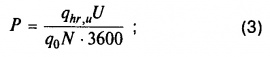
Where: q with hr, u is the rate of water consumption by the consumer per hour of greatest water consumption; l, adj.Z (2); q with o -second flow rate, l / s, with a sanitary device (fittings), adj.Z (2); U-number of water consumers (residents); N-number of water fittings on the site; The number of consumers, U, in modern residential buildings is determined either by the average population of apartments (n sq) or health standards living space f and the entire living space F in the building:
U \u003d u o * n q, or U \u003d F / f (3)
In the absence of data on the number of sanitary appliances in buildings, the values \u200b\u200bof F can be determined by taking N \u003d P. In the absence of data on water consumption and technical specifications sanitary appliances in residential and public buildings, it is allowed to take q tot \u003d 0.3 l / s, and for cold or hot water (q s) q h \u003d 0.2 l / s. The total water consumption rate q tot u is adopted according to Appendix 3 (2) depending on the improvement of the building, which is characterized by the water consumption per capita per day of highest water consumption. Since the values \u200b\u200bincluded in the probability formula for a particular building are constant, the values \u200b\u200bof P entered in column 4 of Table 4 will be constant in all areas where q o does not change. In column 5 of Table 2, the product of the probability value and the number of devices in each calculation section is entered. The maximum second water flow rate in the design section of the network q (q tot ; q h ; q c ), l / sdetermined by the formula:
q p \u003d 5q 0 α, (4)
Where: q 0 - second flow rate of water-folding fittings; α is a coefficient depending on the product of the total number of devices N served by the design section by the probability value of the action P, i.e. α \u003d f (NP); for P\u003e 0.1 and N<2000. α определяется по прил.4 табл.1 ., при других значениях N и Р коэффициент а принимается по прил.4 табл.2 . Расход воды на первых расчетных участках сети следует принимать по расчету, но не менее максимального секундного расхода воды одним из установленных санитарно-технических приборов. Вычисленные величины α и q p для каждого участка сети записываются соответственно в графы 6 и 7 расчетной таблицы. По вычисленному расчетному расходу и принятым скоростям назначают диаметр трубопроводов на расчетном участке. Скорость движения воды в магистральных трубопроводах и стояках рекомендуется принимать не более 1,5 м/с, а в подводках к водоразборным устройствам - не более 2,5 м/с. По рекомендации НИИ санитарной техники, экономичными можно считать скорости 0,9-1,2 м/с, а в трубопроводах производственных водопроводов - не более 1,2 м/с. Диаметры труб обычно назначают по расчетным расходам и рекомендованным скоростям движения воды, пользуясь таблицами (Шевелев Ф.А.,Шевелев А.Ф. Таблицы для гидравлического расчета водопроводных труб.- М.: Стройиздат, 1984.)
table 2
| Plot number | Land length, m | Speed, | Pressure loss |
||||||||
| hydraulic control. incl., i | on the site, h ℓ | in local resistance, h ms |
|||||||||
h ℓ \u003d i * ℓ, (5)
Where: ℓ - length of the calculated section of the pipeline of this diameter, m; i- hydraulic slope. The loss of pressure per unit length is greater, the smaller the diameter and the greater the flow rate of water. Local friction pressure losses in internal water supply networks make up 10-30% of pressure losses along the length of pipes. The calculated values \u200b\u200bare entered in columns 11 and 12. The total pressure loss in the network is :
H 1 \u003d H 2 + H 3 + H f (6)
Where : Н 2 - the height of the water consumption point from the earth’s surface, m. Н 3 - pressure losses, m, in the internal network, including losses to overcome local resistance and losses at the inlet and in the water meter; H f – normalized free pressure of the calculated sanitary device, m
H 2 \u003d N + H et. (n-1) + H set (7)
Where: N uz - the height of the floor of the first floor of the building from the ground at the hatch of the well of the city water supply, m; H et - floor height, m; n is the number of floors; N mouth - the height of the drafting device drafting device above the floor, m;
H 3 \u003d h ℓ + h m.s. + h iv + h v.u. (8)
Where: h ℓ - pressure loss in the design areas, m; h ms - pressure loss on local resistance, m; h century - pressure loss in the water inlet, m; h vu - pressure loss in the water meter unit, m
h cc \u003d i cc * L cc (1 + c) (9)
I centuries – slope of the water inlet; L centuries – length of water inlet, m; k - coefficient taking into account pressure losses due to local resistance, is taken: 0.3 - in the networks of domestic and drinking water pipelines of residential and public buildings; 0.2 - in the networks of combined household and fire water pipelines of residential and public buildings, as well as in the networks of industrial water pipelines; 0.15 - in the networks of integrated production fire water pipelines; 0.1 - in fire water supply networks.
The building is a two-story residential building. The height of the floors is 3.0m. Basement height - 2.0m. The height of the ground floor is 1.10 m from the ground level. Sanitary equipment - washbasins, toilets, sinks, bathtubs. The roof is pitched. The thickness of the floors is 0.3 m.
Input pressure loss - 12.5 m.
Loss of pressure in the water meter unit - 1.35 m.
Characteristics of external networks.
Water supply: guaranteed pressure - 14m; the diameter of the pipeline is 200mm.
Sewerage: the diameter of the collector is 300mm, the depth of the tray in the well is 4.50m.
Freezing depth –1.4 m, location - Moscow.
Calculation of the building's cold water supply system.
The task of calculating a cold water supply system is to determine the necessary pressure at the point of connection of the city water supply network and to compare the result with the value of the guarantee pressure. Under the condition Н 1 ≤ Н gar - the internal water supply system will operate under the pressure of the city network, i.e. installation of additional pumps is not required. If Н 1 ≥ Н gar - the internal water supply system will not work under the pressure of the city network, i.e. installation of additional pumps required.
Table 1
Initial data
| Water consumers | quantity | Second spending | Hourly expenses | Daily expenses | Note |
||||||||
| General, q tot | Cold water, q c | Hot water, q h | Stocks, q s | General.q tot ohr | Hall. water q hr s | Mountains water, q h ohr | General, q u tot | Hall. water, q u c | Mountains water, q h | ||||
| House | Prol. 3. | SNiP 2.04.01-85 |
|||||||||||
| Washbasin | Appendix 2. | ||||||||||||
| Washing | |||||||||||||
3.1. Cold, hot water supply and sewerage systems must provide water supply and wastewater (flow), corresponding to the estimated number of water consumers or installed sanitary appliances.
3.2. Secondary water consumption , l / s, water folding fittings (device),
assigned to one device, it should be determined:
as a separate device - in accordance with mandatory annex 2;
various devices serving the same water users in the section of the dead-end network, according to the mandatory Appendix 3;
various devices serving different water consumers - according to the formula
P i - the probability of action of sanitary appliances, defined for each group of water consumers in accordance with paragraph 3.4;
q 0i - second water consumption (total, hot, cold), l / s, with water fittings (device), adopted in accordance with the mandatory Appendix 3, for each group of water consumers.
3.3. The maximum second water flow rate in the design section of the network q (q tot, q h, q c) l / s should be determined by the formula
q \u003d 5q 0q 0 (q 0 tot, q 0 h, q 0 c) - second water flow rate, the value of which should be determined in accordance with clause 3.2;
α Appendix 4, depending on the total number of devices N in the calculated section of the network and the probability of their action P, calculated according to clause 3.4. In this table. 1 recommended annex 4 should be guided by P\u003e 0.1 and N<= 200; при других значениях Р и N
coefficient α should be taken according to the table. 2 recommended applications 4.
With known calculated values \u200b\u200bof P, N and q (0) \u003d 0.1; 0.14; 0.2; 0.3 l / s to calculate the maximum second water flow it is allowed to use nomograms 1-4 of the recommended application 4.
| Notes: | 1. Water consumption at the end sections of the network should be taken as calculated, but not less than the maximum second water consumption by one of the installed sanitary devices. |
| 2. Water consumption for technological needs of industrial enterprises should be defined as the sum of water consumption by technological equipment, provided that the operation of the equipment coincides in time. | |
| 3. For auxiliary buildings of industrial enterprises, the q value can be determined as the sum of water consumption for domestic needs according to the formula (2) and shower needs - according to the number of installed shower nets according to mandatory annex 2. |
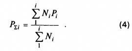
3.4. The likelihood of sanitary appliances P (P tot, P h, P c) on the network sections should be determined by the formulas:
a) with the same water consumers in the building (s) or structure (s) without taking into account changes in the U / N ratio
b) for different groups of water consumers in the building (s) or structure (s) for various purposes
3.5. The maximum second flow rate of wastewater q s, l / s, should be determined:
a) with a total maximum second flow rate of water q tot<= 8 л/с in cold and hot water supply networks serving a group of devices, according to the formula
q s \u003d q tot + q 0 s; (5)b) in other cases q s \u003d q tot.
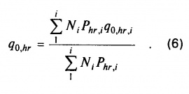
3.6. Hourly water consumption with a sanitary appliance q 0, hr (q tot 0, hr, q h 0, hr, q c 0, hr) , l / h, it is necessary to determine:
a) with the same water users in the building (s) or structure (s) in accordance with mandatory annex 3;
b) with different water consumers in the building (s) or structure (s) - according to the formula
3.7. The probability of using sanitary equipment for the system as a whole should be determined by the formula
P hr \u003d 3600P; q 0 / q 0, hr, (7)3.8. The maximum hourly water flow rate q hr (q tot hr, q h hr, q c hr) cubic m / h, should be determined by the formula
q hr \u003d 0.005 q 0, hr α hr, (8)α hr - coefficient determined in accordance with the recommended Appendix 4 depending on the total number of devices N serviced by the designed system and the probability of their use, calculated in accordance with clause 3.7.
In this table. 1 recommended annex 4 should be guided by\u003e 0,1 and N<=200, при других значениях и N коэффициент следует принимать по табл. 2 рекомендуемого приложения 4 .
3.9. Average hourly water consumption q T (q tot T, q h T, q c T) , m3 / h, for the period (day, change) of maximum water consumption T, h, should be determined by the formula
3.10. When designing directly a drawdown from pipelines of a heating network for the needs of hot water supply, the average temperature of hot water in the standpipes should be maintained at 65 ° C, and the consumption rates of hot water should be adopted in accordance with the mandatory Appendix 3 with a coefficient of 0.85, while the total amount of water consumed should not be changed .
3.11. The maximum hourly flow rate of wastewater should be taken equal to the estimated flow rate determined in accordance with clause 3.8.
3.12. The daily water consumption should be determined by summing the water consumption by all consumers, taking into account the water consumption for irrigation. The daily flow rate of wastewater must be taken equal to water consumption without taking into account the flow rate of water for irrigation.
3.13. Heat flow Q T h (Q hr h) , kW, for the period (day, change) of maximum water consumption for the needs of hot water supply (taking into account heat losses) should be calculated by the formulas:
a) during the average hour
b) during the hour of maximum consumption
| SNiP 2.04.01-85 “Internal water supply and sewerage of buildings” | |
|---|---|
| 1 | General Provisions |
| 2 | Water quality and temperature in water supply systems |
| 3 | Determination of estimated water consumption in water supply and sewage systems and heat for the needs of hot water supply |
| 4 | Cold Water Plumbing Systems |
| 5 | Hot Water Plumbing Systems |
| 6 | Fire water supply systems |
| 7 | Calculation of the cold water supply network |
| 8 | |
At the beginning of the explanatory note, the task should be placed on the course design, then - a table of contents indicating sections and page numbers. At the end of the settlement and explanatory note is a list of used literature, which should be referenced in the text.
The drawings (volume of 2 standard sheets) should include: a city plan with horizontally laid water pipes and a water supply network, a water tower (WB), the location of the water intake structure, pump station I lift (N. St. I item), sites of water treatment facilities (WWTP) with a pumping station II lift (N. St. II p.) in a scale of 1: 5000. The nodes of the water supply network in the drawing should be numbered, and at the settlement sites and water conduits should be
the length and diameter of the pipes are indicated;
piezo lines from N. St. II n. To the most remote and highly located point for all calculated cases;
wiring diagram of the main nodal wells, specification of pipes, fittings and fittings.
The primary task in the calculation and design of the elements of the water supply system is to determine the volume of water supplied to various consumers.
All types of water consumers are reduced to several main categories: household and drinking needs of the population; water consumption for irrigation of streets, squares and green spaces;
water consumption for local industry needs and unaccounted for expenses;
drinking and drinking needs and showering by workers and employees during their stay in production;
water consumption for the technological needs of enterprises receiving it from the city water supply network;
water consumption for fire fighting needs.
Estimated (average for the year) daily water flow Q days. Wed , m3 / day., for household and drinking needs of the population is determined by the formula
Q days avg. \u003d q wN w / 1000, |
where q W - specific water consumption, taken according to the table. 1; N f - estimated number of residents in residential areas with varying degrees of improvement.
Specific water consumption is given in table. 1 and is taken depending on the improvement of residential areas and climatic conditions.
Table 1 |
||
Specific water consumption |
||
The degree of improvement of areas | Specific drinking |
|
water consumption in populated |
||
residential development | points per inhabitant |
|
(daily average for a year), l / day. |
||
Construction by buildings equipped with internal | ||
water supply and sewerage: | ||
with bathrooms and local water heaters | ||
with centralized hot water supply | ||
The estimated water consumption per day with a maximum and minimum water consumption of Q day, m3 / day, will be:
Q days Max | K day max Q day Wed; | ||
Q days min | K day minQ day wed |
||
where K day is the coefficient of daily unevenness, taken in accordance with paragraph 2.2. .
K days.max \u003d 1.1 ... 1.3; K days min \u003d 0.7 ... 0.9.
Estimated hourly water flow rates q h, m3 / h, are determined by the formulas
q hours max \u003d K hours max Q days Max | ||||
q hr min \u003d K hr min. Q days. min / | ||||
where K h - the coefficient of non-uniformity of the hour, is determined by the formulas |
||||
K h max | \u003d α max β max; | |||
K hr min | \u003d α min β min, | |||
where α is a coefficient taking into account the degree of improvement of buildings, the operation of enterprises, etc. It is adopted in accordance with clause 2.2.
α max \u003d 1.2 ... 1.4; α min \u003d 0.4 ... 0.6;
β - coefficient taking into account the number of inhabitants in the village, taken according to the table. 2.
table 2
The values \u200b\u200bof the coefficient β
Number of inhabitants, thousand people | ||||||||||||
β max | ||||||||||||
β min | ||||||||||||
Maximum and minimum second flow rates, l / s:
q s Max | Q hours max / 3.6; | |||
q s min | q hr min / 3.6. |
|||
In the table. 3. The distribution of the maximum daily water consumption by the population by the hours of the day,% of Q days, is given. max
Table 3
Distribution of the maximum daily water consumption by the population by the hours of the day,
% of Q days Max
Hours of the day | K h max | ||||||||||
where q floor is the specific daily average for the irrigation season, water consumption per inhabitant, l / day.
According to the table. 3, note 1 q floor \u003d 50 ... 90 l / day., Depending on climatic conditions.
It is conditionally accepted that watering in the amount of 80% of Q is irrigated by machines for 12 hours, and 20% by wipers for 6 hours a day.
Hourly water consumption for irrigation q h, m3 / h, are:
Water consumption for irrigation is determined separately for each district of the city.
3.3. Water consumption for local industry
and unaccounted expenses
According to paragraph 2.1., Note. 4 water consumption for the needs of local industry and unaccounted expenses Q n. p, m3 / day. It is allowed to take in the amount of 10 ... 20% of the maximum daily consumption for household and drinking needs of the population separately for each region.
Q n p \u003d | (10 - 20%) Q day. Max | |||
Unaccounted expenses are distributed evenly by the hours of the day.
The consumption of water by workers and employees during their stay at the production consists of drinking water consumption and consumption for showering. The nature of production, the number of shifts per day and the number of workers in hot and cold workshops are indicated in the assignment for course and diploma design.
Estimated water consumption for drinking needs per shift
Q see household. pit, m 3 is equal to:
where q cold and q mountains are the norms of water consumption for household and drinking needs per worker working in cold and hot shops, respectively, l / cm., are taken in accordance with § 2. In cold shops 25 l / cm. for 1 person with a coefficient of hourly irregularity K h \u003d 3, in hot shops - 45 l / cm.
N Hall 1000
N mountains 1000 60
Saratov State Technical University
WATER SUPPLY AND WATER DISPOSAL OF RESIDENTIAL BUILDING
Guidelines
to course design
for students of specialties 290800, 290300, 290600, 290700
Approved
Publishing Board
Saratov State
technical university
Saratov 2011
INTRODUCTION
The guidelines are intended for students of specialties 290300, 290600, 290700, 290800. According to the curriculum, students of specialties 290700, 290800 carry out the course project "Water supply and sanitation of a residential building", specialties 290300 - course work on the same topic, and students of the specialty 290600 - settlement and graphic work.
The implementation of the course project (term paper) provides for independent work with educational, normative and reference literature in order to better assimilate the knowledge gained in the study of the discipline and to acquire skills in solving practical and engineering problems in water supply and sanitation.
In the course project carried out by students of specialties 290700, 290800, the design of water supply and sanitation is carried out for residential buildings with the number of floors 7 - 11. In the course and design and graphic work performed by students of specialties 290300, 290800, the design of water supply and sanitation is performed for residential buildings with number of floors 4 - 6.
The paper does not consider the design of local installations for the treatment and pumping of wastewater, which are mainly provided for in special buildings.
Design of water supply and sanitation is carried out in mutual coordination.
Design of water supply for a residential building is carried out in accordance with the requirements of SNiP 2.04.01-85 and SNiP 2.04.02-84.
The design of the sewage of a residential building is carried out in accordance with the requirements of SNiP 2.04.01-85 and SNiP 2.04.03-84.
WATER SUPPLY DESIGN
Domestic water supply
The internal water supply systems of a residential building include: entrances to buildings, water metering units, a distribution network, risers, connections to sanitary devices, water, mixing, mixing, stop and control valves and installations to increase the pressure of water in the network.
Most often, dead-end network circuits are used for domestic and drinking water pipelines.
Enter the water supply.The input of the internal water supply is considered to be the section of the pipeline connecting the external water supply with the internal water supply network to the water meter unit or stop valves located inside the building. The number of inputs depends on the mode of water supply to consumers. Each water supply inlet in residential buildings is designed for a number of apartments of no more than 400. It is advisable to lay it in the middle of the building at right angles to the wall of the building.
The pipeline section from the input to the external network is laid with a slope of at least 0.002 towards the external network.
In dry soils, when crossing walls or foundations, it is recommended that the bushings be laid in cases made of steel pipes, followed by sealing with a resin strand and crushed clay, and on the outside with cement mortar.
The depth of the input is prescribed depending on the depth of the pipes of the street water supply network and the depth of freezing of the soil.
The horizontal distance in the light between the inlets of the drinking water supply and the outlets of sewers and drains should be at least 1.5 m with an inlet diameter up to 200 mm.
Water metering unit. The water meter unit is used to measure the amount of water supplied to the building, and consists of a water meter and fittings necessary to turn it off. A water meter is installed on the pipeline between two valves or valves, as a result of which a water meter assembly is formed.
Meters at cold water inlets should be installed near the outer wall of the building in a convenient and easily accessible room with artificial or natural light and an air temperature of at least 5 ° C. If it is impossible to place the meters in the building, it is allowed to install them outside the building in special wells.
Vane meters are installed only horizontally, and turbine meters in any position. On each side of the meters, straight sections of pipelines should be provided, the length of which is determined
in accordance with GOST standards for water meters, valves or gate valves. A drain valve should be installed between the meter and the second (by the movement of water) valve or gate valve.
A bypass line at the cold water meter is mandatory if there is one input to the building, as well as in cases where the meter is not designed for the calculated water flow rate for internal fire fighting. The bypass line should be counted on the maximum (taking into account fire) water flow. On the bypass line, it is necessary to provide for the installation of a valve sealed at the usual time in the closed position.
Pump installation. The pump installation on the internal water supply is necessary with a constant or periodic lack of pressure, usually when the water does not reach the upper floors of the building through pipes. The pump adds the necessary pressure in the water supply. The most commonly used pumps are centrifugal pumps driven by an electric motor. The minimum number of pumps is two, of which one is operational and the other is standby.
Check valves prevent back pressure on the pump of water from the building, and also protect against unwanted circulation. The bypass line of the pump unit, in contrast to the water meter assembly, on the contrary, is always open. This is due to the fact that during periods of sufficient pressure from the external network, pump operation is not required. Then the pump is turned off with an electric gauge, and water enters the building through the bypass line.
Regulating capacities. Regulating tanks are water and hydropneumatic tanks.
Water tanks, round or rectangular, are made of steel sheet. To prevent overheating of water in the summer and condensation in the winter, the tanks are covered with a layer of thermal insulation from the outside. To collect water that may leak from the tank and condensate resulting from insufficient thermal insulation, a pan is installed under the tank.
Hydropneumatic cylindrical tanks with spherical bottoms are filled with water and compressed air, which creates the pressure necessary for lifting water to all consumers.
Typically, hydropneumatic tanks work in conjunction with pumps, forming a hydropneumatic installation.
The distributing network of a water supply system.Distribution networks of the internal water supply are laid, in accordance with SNiP 2.04.01-85, in basements, technical undergrounds and floors, in attics, in the absence of attics - on the ground floor in underground channels together with heating pipes or under the floor with a removable frieze device or under the ceiling top floor.
Pipelines can be attached:
With support on walls and partitions in places of mounting holes;
Based on the basement floor through concrete or brick columns;
With support on brackets along walls and partitions;
With the suspension on the floor.
In basements and technical undergrounds, pipes Ø 15, 20 or 25 mm are connected to the water supply distribution networks, which supply water to the irrigation taps, which usually lead out into the niches of the basement walls outward at a height above the ground of about 0.30 ... 0.35 m. Watering around the perimeter of the building cranes are placed in increments of 60 ... 70 meters.
Water risers. A riser is any vertical pipeline. Water risers are placed and constructed according to the following principles:
1. One riser per group of nearby water taps.
2. Mostly in bathrooms.
3. On the one hand from a group of nearby water-lifting devices.
4. The gap between the wall and the riser is 3-5 cm.
5. At the base of the riser, a shut-off valve is provided.
Floor liners. Floor-by-floor (apartment-by-apartment) eyeliners supply water from risers to water-folding and mixing fittings: to taps, mixers, valves of flushing tanks. Diameters of eyeliners are usually taken without calculation of Ø 15 mm. This is due to the same diameter of the water folding and mixing fittings.
A shut-off valve Ø 15 mm and a residential water meter VK-15 are installed directly near the riser on the inlet. Next, they bring the pipes to the taps and mixers, and they lead pipes at a height of 0.2 m from the floor. In front of the flushing tank, an additional valve is installed on the eyeliner for manual adjustment of the pressure in front of the float valve.
Water folding and mixing fittings. Water-folding and mixing fittings are used to obtain water from the water supply. It is installed at the ends of the pipelines of pipelines at a certain height above the floor, regulated by SNiP 3.05.01-85.
Water supply calculation
Determination of estimated costs of cold water
1. The maximum daily consumption of cold water, l / day, is determined by the formula
![]() , (1.1)
, (1.1)
where - the general rate of water consumption by the consumer per day of greatest water consumption (from the task - the rate of water consumption), l / day;
- the rate of consumption of hot water by the consumer per day of greatest water consumption, l / day, the value of which should be determined in accordance with Appendix 1;
- the number of water consumers in the whole house (determined based on the fact that there is one resident for each living room).
2. The maximum second flow rate of water in the design section of the network ![]() , l / s, is determined by the formula
, l / s, is determined by the formula
where ![]() - second cold water flow with a sanitary device (fittings), l / s, the value of which should be determined in accordance with Appendix 1;
- second cold water flow with a sanitary device (fittings), l / s, the value of which should be determined in accordance with Appendix 1;
- dimensionless coefficient, depending on the total number of devices in the calculated area of \u200b\u200bthe network and the probability of their action, determined by Appendix 2.
The likelihood of sanitary appliances ![]() on network sections is determined by the formula
on network sections is determined by the formula
 , (1.3)
where is the consumption rate of cold water by the consumer per hour of greatest water consumption, l / h, is taken according to Appendix 1;
where - the general rate of water consumption by the consumer per hour of greatest water consumption, l / h, is taken according to Appendix 1;
- the rate of consumption of hot water by the consumer per hour of greatest water consumption, l / h, is adopted in accordance with Appendix 1;
- the number of water-folding devices.
The number of water-folding devices is determined by the formula
![]() , (1.5)
, (1.5)
where is the number of water taps in one apartment.
3. Maximum hourly water flow ![]() , m 3 / h, should be determined by the formula
, m 3 / h, should be determined by the formula
![]() , (1.6)
, (1.6)
where is the flow rate of cold water with a sanitary appliance, l / h, taken in accordance with Appendix 1;
- a dimensionless coefficient depending on the total number of devices serviced by the designed system and the probability of their use, determined in accordance with Appendix 2.
The probability of using sanitary equipment for the system as a whole should be determined by the formula
 . (1.7)
The maximum hourly flow rate is used when calculating the hydropneumatic booster system.
1.2.2. Selection of a water meter (water meter)
Before choosing a water meter, it is necessary to determine the estimated water consumption: maximum daily, average hourly and maximum hourly.
The maximum daily water consumption, m 3 / day, for water supply needs is determined by the formula
![]() . (1.8)
. (1.8)
Average hourly water consumption, m 3 / h, per day of maximum water consumption
The operational parameters of high-speed water meters are presented in table 1.1.
The diameter of the conditional passage of the water meter should be selected based on the total hourly average water flow per day of maximum water consumption, which should not exceed the operating flow for the meter of this caliber, shown in table 1.1, and the pressure loss in it.
From internal pipelines, drains are transported by external ...
Each apartment, like every family, has its own characteristics, so it is difficult ...