


What winter holidays would be complete without a mountain of tangerines and a couple of juicy...


Despite the rapid development of the Internet, television remains the main source of information for the majority of the population. But in order for your TV to have a high-quality picture, you need a good antenna. It is not at all necessary to buy a television antenna in a store, because you can make it yourself and save a lot of money.
You can find out how to make high-quality antennas for various broadcast bands and what materials to use by reading our article.
There are many types and forms of television antennas, the main ones are listed below:


 Array antennas
 The whole world, including our country, has switched from analogue to digital broadcasting. Therefore, when making an antenna with your own hands or buying it in a store, you need to know which antenna is best suited for receiving DVB-T2 format:


If you live not far from a TV tower, then you can easily make a simple antenna for receiving a signal in DVB-T2 format with your own hands:
The antenna is ready! It should be noted that such a primitive antenna is not capable of providing a high-quality and stable signal at a distance from the TV tower and in places with sources of interference.
Let's look at several options for television antennas that you can make yourself from scrap materials:
An antenna from beer cans can be made in literally half an hour, using the materials you have on hand. Of course, such an antenna will not provide a super-stable signal, but for temporary use in a country house or in a rented apartment it is quite suitable.
 Beer can antenna
 To make an antenna you will need:
After making sure that you have all the above items in stock, do the following:
There are other variations of this antenna, with four and even eight banks, but no obvious effect of the number of banks on the signal quality has been identified.
You can also learn how to make an antenna from beer cans from the video:
The antenna received its name in 1961, after the name of its inventor Kharchenko K.P., who proposed using zigzag-shaped antennas to receive television broadcasts. This antenna is very well suited for receiving digital signals.
 Antenna Kharchenko
 To make a zigzag antenna you will need:
First you need to make an antenna frame. To do this, take the wire and cut off a piece of 109 centimeters. Next, we bend the wire so that we get a frame of two parallel rhombuses, each side of the rhombus should be 13.5 centimeters, make loops from the remaining centimeter to fasten the wire. Using a soldering iron and solder, connect the ends of the wire and close the frame.
Take the cable and strip its end so that you can solder the rod and cable shield to the frame. Next, solder the rod and cable shield in the center of the frame. Please note that the screen and the rod should not touch.
Place the frame on the base. The distance between the corners of the frame at the junction with the cable should be two centimeters. Make the size of the base approximately 10 by 10 centimeters.
Strip the other end of the cable and install the plug.
If necessary, attach the antenna base to a stand for further installation on the roof.
You can watch more detailed instructions for making the Kharchenko antenna in the video:
To make the antenna you will need a 75 ohm coaxial cable with a standard connector. To calculate the cable length required for the antenna, you need to find out the digital broadcasting frequency and divide it in megahertz by 7500, and round the resulting amount.
 Cable antenna
 Once you have the cable length, do the following:
You can visually consolidate the information by watching the video:
It’s worth mentioning right away that to receive a satellite signal you need a tuner and a special set-top box. Therefore, if you do not have this equipment, then creating a satellite dish with your own hands will not be possible, since you yourself can only make a parabolic reflector:

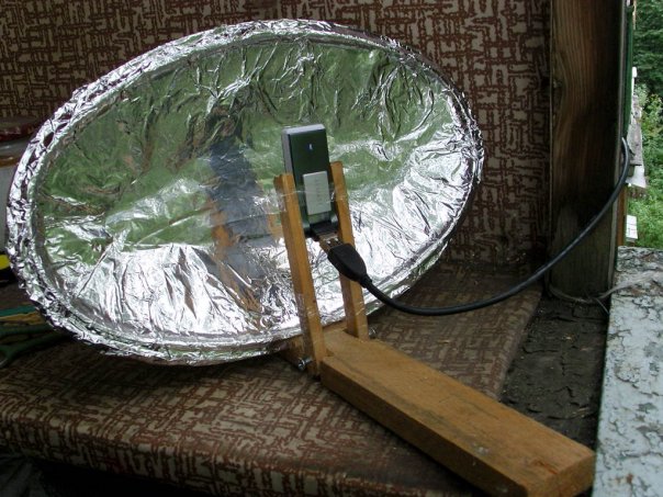
All of the methods listed above can be considered seriously only out of sporting interest, since making a parabolic reflector by hand is a very labor-intensive and expensive process. In addition, it is very difficult to accurately calculate the parameters of a satellite dish at home. Therefore, we advise you not to be original and buy a complete satellite dish.
If the place where you live has a weak television signal and a conventional antenna cannot provide a high-quality picture on your TV, then an antenna amplifier can help in this situation. You can make it yourself if you have a little knowledge of radio electronics and know how to solder. 
Amplifiers should be installed as close to the antenna as possible. It is better to power the antenna amplifier via a coaxial cable through a decoupler.
 Isolation power circuit
 The decoupler is installed at the bottom of the TV and is supplied with 12 volt power from the adapter. Two-stage amplifiers consume a current of no more than 50 milliamps; for this reason, the power of the power supply should not exceed 10 watts.
All connections of the antenna amplifier on the mast must be made by soldering, since the installation of mechanical connections will lead to their corrosion and rupture during further operation in an aggressive external environment.
There are times when you have to receive and amplify a weak signal in the presence of powerful signals from other sources. In this case, both weak and strong signals arrive at the amplifier input. This leads to blocking the operation of the amplifier or switching it to a non-linear mode, mixing both signals, which is expressed in the overlay of the image from one channel to another. Reducing the amplifier supply voltage will help correct the situation.
Please note that UHF amplifiers are greatly influenced by signals in the meter range. To weaken the impact of meter signals, a high-pass filter is placed in front of the UHF amplifier, which blocks meter waves and transmits only signals in the decimeter range.
Below is a diagram of a VHF antenna amplifier:
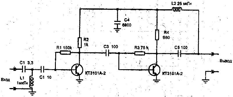 VHF antenna amplifier circuit
 We also suggest that you familiarize yourself with the circuit of the decimeter amplifier:
 UHF amplifier circuit
 You can see the operating principle of the antenna amplifier in the video:
Now, having familiarized yourself with the diagrams and armed with a soldering iron, you can safely begin making an antenna amplifier.
We hope that our article about television antennas was useful to you!

The era of digital signals has arrived. All broadcast television companies began to work in a new format. Analog TVs are reaching their end. They are still in working order and are found in almost every family.
In order for older models to successfully complete their service life, and for people to be able to use them when watching digital broadcasting, it is enough to connect the DVB-T set-top box to the TV receiver and pick up the TV wave signals with a special antenna.
Any home craftsman can not buy an antenna in a store, but make it with his own hands from available materials for watching digital TV programs at home or in the country. The two most accessible designs are described in this article.
Any television signal propagates in space from the emitters of the transmitting television tower to the TV antenna by an electromagnetic wave of a sinusoidal shape with a high frequency, measured in megahertz.

When an electromagnetic wave passes through the surface of the receiving beams of the antenna, a voltage V is induced in it. Each half-wave of a sinusoid forms a potential difference with its own sign.
Under the influence of an induced voltage applied to a closed receiving circuit of the input signal with resistance R, an electric current flows in the latter. It is amplified and processed by the digital TV circuit and output to the screen and speakers as image and sound.

For analog models of TV receivers, an intermediate link works between the antenna and the TV - a DVB-T set-top box, which decodes digital information of an electromagnetic wave into a normal form.
In television broadcasting, state standards require electromagnetic waves to be emitted in only two planes:

In this way, transmitters send emitting signals.
And users simply need to rotate the receiving antenna in the desired plane to maximize the power potential.
TV transmitters propagate their signal waves over short distances, limited by the line of sight from the top point of the TV tower emitter. Their range rarely exceeds 60 km.
For such distances, it is enough to provide a small power of the emitted TV signal. But, the strength of the electromagnetic wave at the end of the coverage area should form a normal voltage level at the receiving end.
A small potential difference, measured in fractions of a volt, is induced at the antenna. It creates currents with small amplitudes. This imposes high technical requirements on the installation and quality of manufacturing of all parts of digital reception devices.
The antenna design should be:
The main parameter influencing the quality of the received digital signal, as can be seen from the explanatory first figure, is the length of the electromagnetic wave of radiation. Under it, symmetrical arms of vibrators of various shapes are created, and the overall dimensions of the antenna are determined.
The wavelength λ in centimeters can be easily calculated using a simplified formula: λ=300/F. It is enough just to find the frequency of the received signal F in megahertz.
To do this, we will use a Google search and ask it for a list of regional TV communication points for our area.
As an example, a fragment of a data table for the Vitebsk region is shown with the transmitting center in Ushachi highlighted in red.

Its wave frequency is 626 megahertz, and its polarization type is horizontal. This data is quite sufficient.
We carry out the calculation: 300/626=0.48 m. This is the length of the electromagnetic wave for the antenna being created.
We divide it in half and get 24 cm - the desired half-wave length.
The tension reaches its maximum value in the middle of this section - 12 cm. It is also called amplitude. The whip antenna is made to this size. It is usually expressed by the formula λ/4, where λ is the electromagnetic wavelength.
It will require a piece of coaxial cable with a characteristic impedance of 75 Ohms and a plug for connecting the antenna. I managed to find a ready-made two-meter piece in the old stock.

I cut off the outer shell from the free end with a regular knife. I take the length with a small margin: when setting up it is always easier to bite off a small piece.

Then I remove the shielding layer from this section of the cable.


The work is done. All that remains is to insert the plug socket into the connector on the TV signal set-top box and direct the bare wire of the inner core across the incoming electromagnetic wave, taking into account horizontal polarization.

The antenna should be placed directly on the window sill or secured to the glass, for example, with a piece of tape, or tied to the blind mount. Reflected signals and interference can be shielded with a strip of foil located a short distance from the central core.
Such a design can be done in literally ten minutes and does not require any special material costs. It's worth trying. But, it is capable of working in an area of reliable signal reception. My building is screened by a mountain and a multi-story building. The transmitting television tower is located at a distance of 25 km. Under these conditions, the digital electromagnetic wave is reflected many times and is poorly received. I had to look for another technical solution.
And for you on the topic of this design, I suggest you watch the video by the owner of Edokoff “How to make an antenna for digital TV”
To receive analogue television signals of various wave frequencies, the design of a zigzag broadband antenna, which does not require complex manufacturing, worked well for me before.
I immediately remembered one of their effective varieties - the Kharchenko antenna. I decided to use its design for digital reception. I made the vibrators from a flat copper bar, but it’s quite possible to get by with round wire. This will make it easier to bend and straighten the ends.

Online calculator
Let's use the all-knowing Google search. We write on the command line: “Calculation of the Kharchenko antenna” and press Enter.

We choose any site you like and perform online calculations. I went into the first one that opened. This is what he calculated for me.

I presented all his data with a picture indicating the size of the Kharchenko antenna.

I took the information provided as a basis, but did not accurately maintain all the dimensions. I know from previous practice that the antenna works well in the broadband wavelength range. Therefore, the dimensions of the parts were simply slightly increased. The half-wave of each harmonic of the sine wave of the electromagnetic TV signal will fit into the arm of each vibrator and will be received by it.
Based on the selected data, I made blanks for the antenna.

The connection of the ends of the figure eight busbar is created in the center at the bending stage. I soldered them with a soldering iron.

I created it according to the “Moment” principle, made it with my own hands from old transformers, and has been working for two decades. I even soldered 2.5 square copper wire with it in thirty-degree frost. Works with transistors and microcircuits without burning them out.
In the near future I plan to describe its design in a separate article on the website for those who also want to make it themselves. Follow publications, subscribe to notifications.
I simply soldered the copper core and braid to the metal of the figure eight from different sides in its center.

The cable was tied to a copper bar, bent into a loop in the shape of a semi-square vibrator. This method matches the resistance of the cable and antenna.
In fact, the Kharchenko antenna often works normally without signal shielding, but I decided to show its manufacture. For the base I took a wooden block. I did not paint or varnish: the structure will be used indoors.
In the back side of the block I drilled holes for attaching the screen wires and inserted them, and then wedged them.

The result was a screen for the Kharchenko antenna. In principle, it can be made of a different design: cut from a piece of frontal armor of a tank or cut from food foil - it will work approximately the same.

On the back side of the bar I secured the vibrator structure with a cable.

The antenna is ready. All that remains is to install it on a window to work in vertical polarization.

When a television receiver is located at a great distance from the transmitting generator, the power of its signal gradually weakens. It can be increased by special electronic devices - amplifiers.
You just need to clearly see the difference between the signals received by the antenna, which can be:
In both cases, the amplifier will fulfill its role and increase the power. Moreover, the TV will clearly perceive and display a weakened signal, but with an amplified signal, playback problems will arise.
The waves are designed to eliminate such interference:
They must be measured with an oscilloscope, and the methods of using various designs must be analyzed individually in each specific case. The antenna is not to blame here.
So, imagine this situation: in the evening you decided to watch your favorite TV program, and suddenly the TV stopped showing. Or another case: You arrived at the dacha, have already prepared for a vacation, and again the same situation - not a single channel works. What to do in this case? The answer is simple - you need to make an antenna for the TV with your own hands, because most likely the cause of the breakdown is in this device. Next, we will look at the simplest creation options, which will require a minimum of available tools and time.
This version of a homemade television antenna is the simplest and fastest to manufacture. The maximum number of channels that will be provided to you is 7, but this figure may vary slightly depending on the region.
To make a TV antenna from beer cans, you will need the following materials:
Finding all the materials in the house will not be a problem, so having prepared them, we immediately get down to business.
In order to make a homemade antenna from cans, you need to complete the following steps:


As you can see, the whole process is quite simple and does not represent anything complicated. The optimal distance is 75 mm between the ends of the cans, and the best installation location is near the window. In individual cases, the distance between banks can be made larger or smaller.
Another equally good option that is advisable to use in the village is a homemade antenna made of copper wire with an amplifier.
All you need for production is:
So, to make your own TV antenna from copper wire, you need to complete the following steps:


Please note that in the photo examples, both the amplifier, the reflector, and the wire are covered with paint. Painting protects the structure from corrosion and other adverse factors, significantly extending the life of a homemade TV antenna.
Idea No. 3 – Home HDTV device
If the first 2 options worked at a frequency of no more than 270 MHz, then the next manufacturing method will allow you to enjoy a higher quality picture, because The signal range can reach up to 490 MHz. The only part that is unlikely to be found among household items is a matching transformer from 300 to 75 Ohms. You will need to buy it in advance if you decide to make your own TV antenna as an experiment and improve your skills. Although there are instructions for making a homemade transformer, you can find and use it.
Materials you will need:
Scotch Cardboard Stationery knife Foil Stapler Scissors Marker Roulette Having prepared all this school kit, let's get down to business!
First you need to sketch (or print on your computer) this diagram:
Now, according to the diagram, we cut out all the spare parts, including the necessary pieces of foil:
After this, you need to make a reflector with dimensions of 35 * 32.5 cm (height and width). Cover one side with foil.
In the middle we cut out two identical rectangles, which are necessary in order to completely assemble the signal catcher of a homemade antenna for a TV. The rectangle should be 3.5 cm long, its purpose is to maintain the distance between the reflector and the auxiliary parts.
We glue the parts onto the rectangle, and when the cardboard homemade product hardens, we drill holes for the television cable.
We connect the transformer and insert the cable into the plug. A more powerful TV antenna is ready for use! It should also be noted that this homemade version is only suitable for indoor use, because paper will quickly deteriorate outdoors.
Assembling a digital antenna from a TV cable and a cardboard box
Another option for a powerful device made at home:HDTV antenna made from improvised means
Idea No. 4 – Apartment option
There is another way to make a powerful antenna for a TV from improvised materials, which is suitable for both outdoor and indoor use.
To make the device you will need the following materials and tools:
- 4-meter copper wire, cross-section 4 mm2;
- board of arbitrary thickness, 55 cm long and 7 cm wide;
- wood screws;
- ruler or tape measure;
- a simple pencil;
- screwdriver;
- soldering iron;
- plug
So, first, according to the drawing, we drill holes in the board:
Then we transfer the drawing data to the board and drill in the appropriate fastening points.
In the middle of each of the 37.5 cm sections, the insulation must be removed (as shown in the picture).
We cut off 2 more copper wire sections 22 cm long and roughly divide them into 3 equal parts, again removing the insulation at the inflection points.
We bend the prepared wire in exposed areas. We draw your attention to the fact that for those segments that are bent in half, the distance between the ends should be 7.5 cm (the optimal value for receiving a signal from a homemade television antenna).
Next, we attach the plug to the finished homemade product, and connect the television cable to it.
This concludes the manufacturing process. We select a suitable location and install the device.
So we have provided the simplest instructions. We hope that now you know how to make a home TV antenna with your own hands! We draw your attention to the fact that today on the Internet you can find many other options in which inventors do without cans and wire. Among other available means, copper tubes, aluminum disks and electrodes are often used. The advantage of the options we have listed is that you can quickly make such antennas for a TV with your own hands, without spending the whole evening on it.
Visual video instructions for creating a simple antenna from cans
Assembling a digital antenna from a TV cable and a cardboard box
HDTV antenna made from improvised meansPhoto gallery (38 photos)
Antenna is a radio device designed to receive and emit electromagnetic waves through the air.
If you live within direct visibility of a television tower, then a simple homemade indoor television antenna, the design of which is presented in this article, is quite suitable for receiving digital television. This antenna is designed to receive television broadcasts in the digital television frequency range (470–790 MHz).
The design of a television antenna is simple and does not require special knowledge to repeat. To make it you will need 70 cm of copper wire with a diameter of 2-3 mm, a piece of double-sided fiberglass sheet, 1.5 m of coaxial television cable with a characteristic impedance of 75 Ohms and an F-plug.
Instructions for making a UHF television antenna
The first thing you need to do is select a piece of copper wire with a diameter of 2-3 mm and a length of 70 cm. For these purposes, a single-core copper wire is well suited for laying electrical wiring. If there are several conductors in the cable, then you need to carefully cut off one conductor along the groove, being careful not to damage the insulation. It is not needed for the antenna to work; the insulation is left only for aesthetic appearance.
An aluminum wire will also work, but then it will have to be connected to the contacts of the matching transformer board using a threaded connection. Please note that the nut should not touch the shielding foil of the transformer; if it does, then you need to lay an insulating washer or trim the foil.
If you use a wire without insulation, you can put a vinyl chloride tube on it for beauty.
Next, the wire needs to be bent into a ring with a diameter of approximately 220 mm. High precision is not needed here. A paint bucket holder or any other round container of suitable size works well for this.
When the antenna ring is ready, you can begin manufacturing the printed circuit board for the matching transformer.
The printed circuit board is made of fiberglass or getinax, foil-coated on both sides, 1.5 mm thick, 25x30 mm in size. The photo shows the appearance of the transformer printed circuit board on both sides.
This photo shows a negative of the antenna circuit board. The width of the current-carrying tracks is 1 mm, the distance between the tracks is 1.5 mm. Antenna board size 25×30 mm.
If it is not possible to make a printed circuit board for the manufacture of an antenna using a chemical method, then it can be made mechanically. To do this, you need to remove unnecessary sections of the foil, leaving only the contact pads, and lay out the current-carrying paths from copper wire with a diameter of 0.3-0.5 mm, gluing it to the board, for example, with “Moment” glue.
To give an aesthetic appearance and increase the mechanical strength of the antenna, the transformer is placed in a plastic box in which holes for the ring and antenna cable are pre-drilled.
When all the parts are prepared, you can begin assembling the antenna. The ends of the ring, pre-tinned with solder, are inserted into the box and bent at a right angle at a distance of 3 mm. Next, the ends are inserted into the printed circuit board of the antenna transformer and soldered with solder using a soldering iron.
The antenna board is placed on the bottom of the box and secured with an M3 screw and nut.
You first need to install a television F-connector on one end of it, and cut the other one and solder its ends onto a printed circuit board. The center core of the cable is soldered directly to the right end of the ring, and the braided shielding is soldered directly to the foil of the antenna board.
For reliable operation of the antenna, you need to solder or attach the cable in the following order. First, the shielding braid is soldered, then you need to pull the cable well to remove the slack, and only then solder the central core. In this case, when moving the antenna to find a place in the room with the maximum signal level and stretch the cable, the central core will not break.
If the cable screen is made of aluminum foil, then it can be pressed to the foil of the board using a metal clamp placed on a screw and secured with a nut. The technology for attaching the screen with a clamp is discussed in the article “How to make a TV crab with your own hands.”
All that remains is to close the box with a lid, insert the connector into the TV and tune the channels to the desired programs. In order to ensure image quality with minimal noise, you need to move the antenna around the room to find a place with the maximum television signal.
How to replace the matching printed circuit board
cable loopThe use of a printed circuit board to match the antenna with a coaxial cable allows you to make the antenna more compact.
If there is no desire or opportunity to make a printed circuit board, then without losing the quality of the antenna’s performance, it can be replaced with a loop, which is also called a U-elbow, which is a section of television cable bent in half, connected to the antenna according to the circuit, as in the photograph below.
To make a matching loop, you need to take a piece of television cable 162 mm long, with which the antenna will be connected to the TV. Cut its ends and solder the central cores to the ends of the ring, the distance between which should be 60 mm. Next, the end of the cable going to the TV is cut and its central core is soldered to either end of the antenna ring, and the shielding wire is connected to the shielding wires of the loop, as shown in the photograph.
When soldering the shielding braid, care must be taken so that the insulation of the central core does not melt and the braid does not come into contact with it.
The photo shows the soldering of a cable to an antenna ring made of aluminum wire with a diameter of 3 mm. Since it is difficult to solder wires to aluminum with soft solder, the ends of the ring were slightly flattened, holes were drilled in them, and brass petals were secured with rivets. The central cores of the cable are soldered securely to the petals.
A homemade television antenna is configured to receive over-the-air signals no worse than purchased ones. However, it is distinguished by great quality and efficiency.
Any craftsman can make such a device from scrap materials and install it in a suitable place.
Briefly about modern antennas
Modern receivers operate in the UHF range and are characterized by a high level of signal propagation and the use of low-power sensors.
However, digital television broadcasting is becoming the most popular, which has a number of advantages:
- Resistance to interference or other cable distortions;
- High image clarity and sharpness;
- Ability to select the most interesting channels.
- The simplicity of the design allows you to make such equipment at home and using available materials.
Types of antennas
There are a large number of antenna device options, each of which has its own advantages and disadvantages. Before you start making the receiver, you need to decide on the type of model: all-wave, speech therapy or zigzag.
You can make an all-wave antenna in an hour and from cheap materials. It is frequency independent and perfectly receives the signal within the city, but in settlements remote from powerful receivers it will be useless.
The speech therapy antenna is universal, but not rich in a large number of received channels.
The simple design and average characteristics ensure stable reception.
A Z-shaped antenna will require a large amount of time and materials, which pays off in a wide receiving range.
Required level of training
Despite the simplicity of most antennas, sufficient experience and knowledge of higher mathematics and electrodynamics are still required. This knowledge will help you better understand diagrams and drawings and understand all the terms used.
However, even unprepared but motivated craftsmen have a chance to assemble a high-quality digital antenna.
First of all, you need to familiarize yourself with the photo of the antenna device and the basic terms found in the instructions:
- “KU” – designation of the device’s power strength, indicating the ratio of the received signal to its main “lobe”;
- “KND” is the coefficient of proportion of the area of the antenna’s body circle to the level of inclination of the angle of all lobes of the device;
- “KZD” – correlation of the signal received on the main sheet and the total power of the device.
The following points should also be considered:
- The power of a band antenna depends on the level of the useful signal.
- These characteristics are not always interrelated, which requires special attention when setting up equipment.
- Each element of the device is securely welded or soldered to its neighbor.
- Street units are thoroughly fixed with all kinds of fastenings.
- In places of zero potential, it is mandatory to use solid bent metal.
- Coaxial cable or other corrosion-resistant coaxial cable is most often used as the central core.
- It is recommended to connect the elements with a 40 V soldering machine, while using low-melting solders and flux paste.
- For an outdoor antenna, it is necessary to set up high-quality protection of connections from precipitation, temperature changes and other negative natural influences.
All-wave antenna circuit
To make an all-wave digital antenna you will need 2 triangular metal plates or square fiberglass with a reflective coating, as well as 2 wooden slats with a cross section of 2-3 cm and wire.
- Prepare all the necessary materials and tools, including a soldering or welding machine, wire, ruler, meter, pliers, safety glasses, rope, scissors.
- Place the plates at an angle of 90 degrees so that the width of the device is equal to the height.
- Fix with a soldering iron.
- Attach the cable to the point of zero potential, but do not solder it, but tie it.
Beer can antenna
Beer or soda cans have good reception of digital television signals, which makes them an excellent material for a homemade antenna.
Note!
This material is used to increase the diameter of the arms on a linear vibrator, which enhances the signal quality and makes it possible to connect directly to the cable.
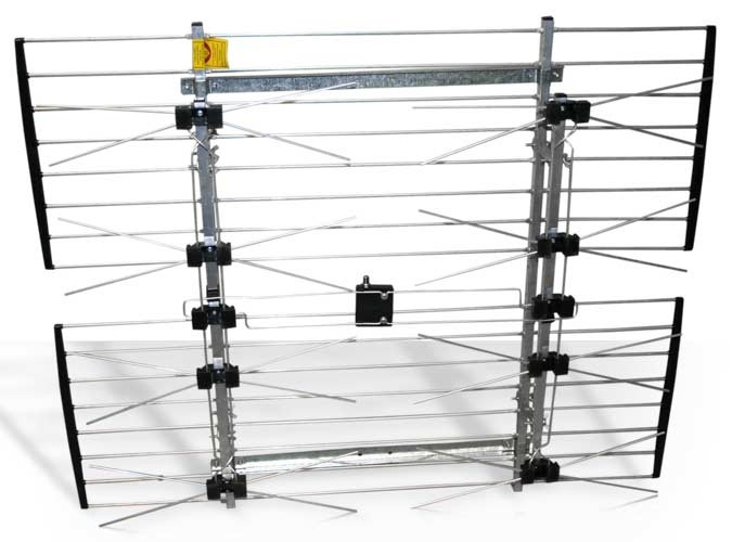
Optimization of an old antenna
To receive a higher-quality digital signal, you can upgrade your analog television antenna and make a T2 receiver out of it. The main requirement will be strict adherence to all dimensions of the equipment: the outer side of the square is 14 cm, the inner side is 13 cm, a gap of 2 cm and a wire 115 cm long. Next, all elements are cleaned, soldered and connected to the television cable.
Having understood the principle of operation of the antenna, you can experiment with its design, tuning into new channels and improving the quality of already received ones.
You can use any materials at hand, for example, to make an antenna for a modem, a box of laser discs will be useful.
DIY antenna photo
Note!
Note!
What winter holidays would be complete without a mountain of tangerines and a couple of juicy...

Amethyst is a quartz mineral with a deep purple-pink color. He...

You can make an imitation of stained glass without using glass, i.e. from colored paper...