Lbvf Reply How it all started, I enter the room behind the brother, sitting naked...


In this post there will be a story about a very interesting rare specimen: the Strela radio receiver, model born in 1958 (now 55 years old). I inherited this brilliant creation of Soviet technicians from my grandmother, to whom I offered to repair it and keep it as a souvenir. Despite such a great age, the device is very well preserved. I remember well how my great-grandmother listened to this receiver in the village, and my father even made a long spiral antenna from copper wire for improved reception of long-distance radio stations. Even then I was wondering what kind of glass tubes it was that glowed inside, which made this cute little box talk and sing)
A lot of time has passed and now this receiver cannot be plugged into a socket, since the conductors have lost their flexibility and simply break when bent, and it is not clear what is going on inside. I took it upon myself to correct this situation...
Having brought this device to my home, I rushed to the Internet to search for a description and diagram of this tube receiver. The radio receiver is a three-tube superheterodyne, which is designed to receive radio stations in the medium wave (MW) and long wave (LW) range. Yes, yes, it was SV-DV, there was no talk of any VHF and FM bands at that time, high-frequency ranges had not yet been conquered enough to mass-produce radios, high-frequency circuits (coils + capacitors) were difficult to manufacture and use.
There is a diagram, from it it is clear that the receiver must have four lamps: 2 lamps (6I1P) for the receiving path, 1 lamp (6P14P) for the ULF and a 6Ts4P kenotron for the rectifier. The ULF output power is about 0.5 Watt, which is quite enough for listening to radio broadcasts loudly. when consumed from a 127-220V network, the power is 40 watts. The price of the radio (in 1961) was 28 rubles. 15 kopecks (by today's standards approximately 300-400 UAH, 40-50 dollars)

Rice. 1. Strela radio receiver, homemade spiral antenna and power plug.

Rice. 2. Strela radio, front view

Rice. 3. Strela radio, rear view

Rice. 4. Strela radio, inside view
So, having removed the back cover, I saw a little dust and a little cobwebs, no rust - this suggests that the device was kept in a fairly clean place with normal humidity and for 50 years everything is OK. The absence of a kenotron rectifier lamp immediately caught my eye, although I could find it, if not at the market, I could order it on the Internet on some forum with old junk. The speaker is connected to an isolation transformer and a blocking capacitor. In addition, the chassis contains a variable capacitor (VCA), which serves to tune to the desired frequency, as well as interesting cylindrical blocks between the lamps with sealed holes.

Rice. 5. The two-core 220V power conductor has not passed the test of time.
The wire for connecting the power with a slight bend simply breaks, it is clear that this “ancient noodle” needs to be changed urgently, it is better not to risk supplying 220V to such a conductor.

Rice. 6. The receiver circuit is assembled using wall-mounted installation (click to enlarge)
Capacitors and resistors are mounted on a common panel made of getinax, and the coils are placed near the contacts of the push-button range switch. On the right, I noticed black diodes wrapped with fabric tape, I immediately realized that this was a diode bridge - a replacement for the kenotron lamp, which was missing))
Okay, we don’t need to look for the lamp anymore, let’s continue our inspection. I noticed very interesting elements near the inductors, which are a thin conductor (0.2-0.3 mm in diameter) wound on a piece of a thick conductor (1-2 mm in diameter), and one of the ends of the wound conductor is not connected anywhere... what could this be? be like this:

Rice. 7. An interesting radio-electronic component, what is it? (click to enlarge)
Quite quickly, without looking at the diagram, I guessed that this was a CAPACITOR with a very low capacitance, which can be precisely adjusted by unwinding and winding turns of a thin wire. A very interesting solution, in this way you can make a homemade capacitor of several picofarads (pF).
I didn’t have to look for a power cord with a plug for long; I took it from a non-working Chinese cassette player.

Rice. 8. New power cable for the radio
Between the lamps there are interesting cylindrical blocks with red paper stickers - when I pulled out the latch and removed the screen, I saw a scarf with coils and tubular capacitors, these are the input circuits of the radio receiver hidden under a cylindrical aluminum screen.

Rice. 9. Block of coils and tubular capacitors of the receiver input circuit
Well, let's try to connect the receiver, solder and secure the power cord, pull the chassis out for debugging:

Rice. 10. Receiver chassis, pulled out of the case

Rice. 11. Food is served, Ser! The lamps are warming up.
After turning on the power, I began to wait for the lamps to warm up; after warming up, after a few more seconds, I heard a hissing in the speaker - Hurray, it worked! Turning the KPI tuning knob, I caught the “Voice of Russia” station and several other powerful stations. By stretching the antenna a little, the number of received stations increased. I did not connect the grounding, although I think that with it the reception became even better.
The 6P14P lamp (far right), which is located in the low-frequency amplifier, gets quite hot, which is not surprising)
![]()
Rice. 11. Speaker and receiver transformer.
On the receiver scale, I noticed small sockets for light bulbs; the scale used to be illuminated. The tester measured the voltage at the sockets - about 6V. You need 6.3V light bulbs, after searching in the trash I found a bag with different micro bulbs for different voltages, I was lucky - 2 of them turned out to be 6.3V!

Rice. 12. Miniature light bulbs for different voltages
We install the light bulbs in their places...

Rice. 13. Illumination of the radio dial on two bulbs

Rice. 14. Illuminated receiver scale in action

Rice. 15. Intel Pentium III, Geforce 8800 GPU, 6P14P lamp - more than 50 years of evolution
After a little cleaning of dust and cobwebs, everything can be put back together and given into the good hands of my grandmother.

Rice. 15. I assembled everything, everything works!
For starters, I present a short video of his work:
The post came out in the form of a story with pictures, I hope it turned out interesting.
The topic of retro receivers, in particular regenerative ones, is being developed comprehensively and very fruitfully on many sites and at one time was very interesting to me. As a result, the idea arose to make a simple, but multi-band, single-tube regenerator, which can subsequently be converted with “little blood” into a simple, but also multi-band, superheterodyne, using a minimum of non-scarce parts.
I bring to your attention a very simple and excellent HF circuit of a single-tube regenerative receiver based on a 6N2P double triode. 
Schematic diagram is shown in Fig. 1. I have tested several options for simple single-lamp regenerators and the one presented here, in my opinion, is the best in many respects and is worthy of repetition.
The design of V. Egorov, “Simple short-wave receiver” (Radio, 1950, No. 3), remarkable for its simplicity and elegance, was taken as a basis. After testing this receiver, its circuit was slightly modified
- OOS was introduced into the second cascade and strengthened in the first (the regenerator itself). This became possible thanks to the use of a specific feature of triodes - relatively high permeability or, if you like, a significant influence of the anode load on the cathode grid, therefore, high-resistance anode resistors create a fairly large “internal” OOS, equivalent to introducing resistance = Ra/u into the cathode, in in our case it is 47 kOhm/100 = 470 ohms, which ensures high stability of the selected mode. The second “function” of cathode bias in ULF is to shift the operating point in the linear section of the current-voltage characteristic so that there is no limitation - this is also not relevant, because Our regenerator has a very small signal at the ULF input (no more than tens of mV).
— High voltage has been removed from the headphones (it’s somehow creepy to realize that 200V is supplied to the head).
— Transition and blocking capacitors now perform the functions of single-link low-pass filters and high-pass filters and are selected to provide a bandwidth of approximately 300-3000 Hz.
- a two-stage attenuator made it possible not only to ensure normal operation of the receiver with any, incl. full-size antenna, but also provided a very soft approach to regeneration (in the original it was a bit harsh, which did not allow for high sensitivity).
As a result, the receiver has high stability (on twenty it holds an SSB station for half an hour/hour, and on eighty I’ve been listening to a group of stations for more than 5 hours without any adjustment!) and sensitivity (on the order of several microvolts - I haven’t figured out how to measure it more precisely yet - hi !), good repeatability (thanks to the OOS, its parameters depend little on the spread of lamp characteristics) and very simple control - with a large frequency tuning, or after switching ranges, I put the attenuator in the middle position, and use potentiometer R3 to achieve the start of generation (a slight click on phones) and that’s all, then, as a rule, I use only two knobs - tuning (KPI) and attenuator - when switched on as indicated in the diagram, it is actually a universal regulator - it simultaneously regulates both the attenuation and the lasing threshold.
Design Features visible in the photo. 
 The case from an old computer power supply was used as a shielded case. As you can see, the chassis was pre-provided with space for a second lamp. The filament power supply has been stabilized. Headphones are electromagnetic, always high-resistance (with electromagnet coils with an inductance of approximately 0.5 H and a direct current resistance of 1500...2200 Ohms), for example, types TON-1, TON-2, TON-2m, TA-4, TA-56m. It is better to use KPE with an air dielectric. Depending on the limits of change in its capacitance and the inductance of your coil, to obtain the required ranges, the values of the stretching capacitors will probably have to be recalculated using a simple program KONTUR3C_ver. by US5MSQ
. To eliminate rustling and crackling, both sections of the control unit are connected in series, and the rotor together with the control unit body must be isolated from the chassis (a kind of differential control unit). For not very high frequencies, you don’t have to bother with insulating the KPI, but in essence it’s very easy to do - I spent half an hour making a bracket from getinax - with all the smoke breaks (hi!).
The case from an old computer power supply was used as a shielded case. As you can see, the chassis was pre-provided with space for a second lamp. The filament power supply has been stabilized. Headphones are electromagnetic, always high-resistance (with electromagnet coils with an inductance of approximately 0.5 H and a direct current resistance of 1500...2200 Ohms), for example, types TON-1, TON-2, TON-2m, TA-4, TA-56m. It is better to use KPE with an air dielectric. Depending on the limits of change in its capacitance and the inductance of your coil, to obtain the required ranges, the values of the stretching capacitors will probably have to be recalculated using a simple program KONTUR3C_ver. by US5MSQ
. To eliminate rustling and crackling, both sections of the control unit are connected in series, and the rotor together with the control unit body must be isolated from the chassis (a kind of differential control unit). For not very high frequencies, you don’t have to bother with insulating the KPI, but in essence it’s very easy to do - I spent half an hour making a bracket from getinax - with all the smoke breaks (hi!).  Despite the fact that, in principle, the regenerator will be able to work (i.e., completely regenerate the circuit) with almost any coil, it is desirable that the inductor have the highest possible design quality factor - this will allow, with the same results, to use less inclusion of the lamp in the circuit, and, accordingly, reduce its destabilizing influence (both itself and indirectly through it the rest of the circuit and power sources). Therefore, it is better to wind the coil on a frame of sufficiently large diameter or, even better, on an Amidon ring (for example T50-6, T50-2, T68-6, T68-2, etc.).
The number of turns to obtain the specified inductance can be calculated using any program, for example, for ordinary frames the program is convenient COIL 32
, and for Amidon rings - mini Ring Core Calculator
. To begin with, the tap location can be taken from 1/5...1/8 (for conventional frames) to 1/10...1/20 (for Amidon) the number of turns of the loop coil.
Regarding replacement of a possible lamp. In this circuit, the “mu” gain is of greater importance, and the low current consumption of the 6N2P is also nice - you can install an effective RC filter along the anode power circuit without bulky chokes or electronic filters/stabilizers - this is exactly what I did and there is no background in the headphones. Therefore, the best replacement would be 6N9S. However, you can use any double triodes (6P1P, 6N3P, etc.) without circuit adjustments and almost without damage (the LF gain will be slightly less (2 times). On the other hand, with a higher anode current and lamp steepness, you can install an output transformer instead of high-impedance headphones and use more affordable modern low-impedance ones with high sensitivity.
About the power supply of the regenerator. The question - whether it is necessary to stabilize the supply voltage (filament and anode) of a lamp regenerator often arises on different branches of the form and the answers to it are often given the most contradictory - from nothing needs to be stabilized and rectified (and so they say, everything works great) to the mandatory use of a completely autonomous , battery power.
And no matter how surprising it is, the statements of both of them are true (!), it is only important to remember the main criteria (or, if you like, requirements) that both authors present to the regenerator. If the main thing is simplicity of design, then why bother with power stabilization? Regenerators of the 20-50s (and these are hundreds (!) of different designs), made according to this principle, worked perfectly and provided quite decent reception, especially on the broadcast bands. But as soon as we put sensitivity at the forefront, and it, as is known, reaches a maximum at the generation threshold - an extremely unstable point, which is influenced by numerous external changes in parameters, and supply voltage fluctuations are among the most significant, then the answer is obvious: if you want to get high results - the supply voltage must be stabilized.
Circuit of a simple two-tube superheterodyne is shown in Fig. 2. This is a four-band receiver, and on 80m it is direct amplification (the VL1.2 pentode works as a UHF decoupler). And on the rest - a superheterodyne with a quartz local oscillator and variable IF. The local oscillator, made on a VL1.1 triode and stabilized by just one non-scarce 10.7 MHz quartz, operates on 40m and 20m on the fundamental harmonic of quartz, and on the 10th range on its third harmonic 32.1 MHz. The mechanical scale with a width of 500 kHz on the ranges 80 and 20 m is direct, and 40 and 10 is reverse (similar to that used in UW3DI). To ensure the frequency ranges indicated in the diagram, the tuning range of the regenerative receiver, which in this case plays the role of the IF path, regenerative detector and ULF, is chosen to be 3.3-3.8 MHz.
When receiving in telegraph (autodyne) mode, the sensitivity (at s/noise = 10 dB) was about 1 µV (10m), 0.7 (at 20 and 40M) and 3 µV (80m).
The dual-circuit PDF is designed according to a simplified design (only two coils), thus ensuring maximum sensitivity at 10 m, and at 80 m - increased attenuation, which also reduces some redundant gain on this range. The coil data is shown there in the circuit diagram. Mounting is mounted, clearly visible in the photo. The requirements for it are standard - maximum rigid mounting and minimum length of HF conductors. 

The setup is also quite simple and standard. After checking the correct installation and DC modes, we switch to the 80m range and set up the regenerative receiver using the method described above. To fit its frequency range, we connect the GSS through a separating capacitance directly to the grid (pin 2) VL1.2. Then to set up the PDF 80m range, for which we switch the GSS to the antenna input, set the average frequency of the range to 3.65 MHz. We switch the regenerator to generation mode (autodyne mode) and by adjusting the KPI, we find the GSS signal. Using the coil cores we adjust the PDF to the maximum signal. At this point, the tuning of the 80m range is completed and we no longer touch the coil cores. Next, we check the operation of the local oscillator. By connecting a tube AC voltmeter to the cathode (pin 7) of VL1.2 to monitor the local oscillator voltage level (if you don’t have an industrial one, you can use a simple diode probe, similar to that described in) or an oscilloscope with a bandwidth of at least 30 MHz with a low-capacitance divider (high-resistance probe) , as a last resort, connect it through a small (3-5 pF) capacitance.
Switching to the 40 and 20m ranges, we check for the presence of an alternating voltage level of about 1-2 Veff. Then we turn on the 10m range and by adjusting C1 we achieve the maximum generation voltage - it should be approximately the same level.
Then we continue setting up the PDF, starting with the 10m range, for which we switch the GSS to the antenna input and set the average frequency of the range to 28.55 MHz. We switch the regenerator to generation mode (autodyne mode) and by adjusting the KPI, we find the GSS signal. And using trimmers C8, C19 (we don’t touch the coil cores!) we adjust the PDF to the maximum signal. Similarly, we configure the ranges of 20 and 40 m, for which, respectively, the average frequencies of the ranges will be 14.175 and 7.1 MHz, and the adjustment trimmers will be C7, C15 and C6, C13.
If you want loud-speaking reception, the receiver can be equipped with a power amplifier made according to standard circuits using 6P14P, 6F3P lamps. 6F5P. Some of my colleagues showed tuning skills in the manufacture of this receiver.
A well made and beautiful receiver performed by Pavel (nickname Pasha Megavolt
) - see photo. 
And there is a receiver with a drawing of a printed circuit board in the design LZ2XL,LZ3NF.
People often ask about connecting a digital scale to this receiver. I would not introduce a digital scale there - firstly, the mechanical scale is quite simple, the calibration is stable, it is enough to carry it out only on one 80m band, and on the rest the markings are drawn with a simple recalculation based on the measured frequency of the stand generator. And secondly, the digital scale itself can become a source of interference if things go wrong, i.e. It will be necessary to carefully think through the design and, probably, introduce shielding of at least the regenerator coil (its sensitivity is a few microvolts!), and possibly also the scale itself.
If you do introduce it, then it’s best to do it like this:
- local oscillator through a source follower on KP303 (KP302,307 or imported BF245, J310, etc.) with a gate through a 1 kOhm resistor directly to pin 7 of VL1
- the regenerator, depending on the PIC adjustment, can have a very low voltage on the circuit (tens of mV), so the regenerator signal will require not only decoupling, but also amplification. This is best done on a two-gate gate type KP327 or import (BF9xx), connected according to the standard circuit (make the bias on the 2nd gate + 4V) and loaded onto a 1 kOhm resistor in the drain. We connect the first gate through a 1kOhm decoupling resistor to pin 3 of VL2.
P.S. A couple of years after its manufacture, I took this two-tube super from the far shelf, blew off the dust and turned it on - it works, and it’s so nice that in two evenings of unobtrusive observations on each of the lower bands (80 and 40m), signals were received from all 10 regions of the former USSR.
Of course, the DD and neighbor selectivity are rather low, but in the first case a smooth attenuator helps, and in the second case, a slight narrowing of the passband (regeneration knob), more radically - a transition to a less populated frequency (hi!), and nevertheless, even in overpopulated sections of the ranges manages, at a minimum, to accept basic information. But its main advantage (besides the simplicity of the design) is very good frequency stability, you can listen to stations for hours without adjusting, and this is with equal success not only on the lower, but also on the 10th range!
I measured the sensitivity - with s/noise = 10 dB it corresponds to the above, and if we are tied to the output signal at a level of 50 mV (the signal on the TON-2 headphones is already quite loud), but it turned out like this,
A shortwave receiver, as we know, “the theater begins with a hanger,” and the path to shortwave begins with listening to amateur bands and observing the operation of amateur radio stations. On short waves, radio amateurs conduct radio communications in the ranges of 160 m (1.81-2.0 MHz), 80 m (3.5-3.8 MHz), 40 m (7.0-7.2 MHz), 30 m ( 10.1-10.15 MHz), 20 m (14.0-14.35 MHz), 17 m (18.068-18.168 MHz), 15 m (21.0-21.45 MHz), 12 m (24. 89-24.99 MHz) and 10 m (28.0-29.7 MHz).
As a rule, the main problem of a beginning shortwave operator is a receiver on the amateur bands, or rather, the lack thereof. Commercially produced HF survey receivers are quite expensive; in addition, almost all models are mainly focused on receiving signals from broadcast radio stations operating in amplitude modulation mode, and do not provide good reception of amateur radio stations using various types of radiation - telegraph (CW), single-sideband modulation with suppressed carrier (SSB) and others (for example, phase-shift keyed, used in digital types of radio communications).
A not very complex homemade HF receiver for the amateur bands can be made by a novice radio amateur, but it should be kept in mind that setting up a homemade receiver is a process that requires an understanding of the operation of both individual components and the design as a whole. Most often, when tuning, you cannot do without a minimum of measuring instruments, so it is advisable to manufacture and configure the receiver under the guidance of a fairly experienced radio amateur or radio electronics specialist.
A receiver developed by a Polish radio amateur. SP5AHT operates on the amateur bands 160, 80, 40, 20, 15 and 10 m and fully meets the requirements for beginner designs. The receiver circuit is quite simple, and the proposed original design makes it easier to replicate the device. The choice of only 6 amateur HF bands was dictated by the number of positions of the small-sized flip switch used. Instead of one or more of the indicated ranges, you can enter others - for example, replace the 10 m range with a 17 m range. The receiver supply voltage is 12-14 V, the current consumption is no more than 50 mA.
The receiver is a superheterodyne with an intermediate frequency of 5 MHz, at which the main selection of received signals is carried out. The main selection filter is quartz, made on 4 small-sized quartz resonators with a frequency of 5 MHz.
The receiver circuit is shown in Fig. An antenna is connected to the receiver via connector XS1. The signals received by the antenna are sent to variable resistor R1, which is used to adjust the volume. Next, through the isolation capacitor C12, the signals are supplied to the input circuit formed by the capacitor C13 and one of the coils L1-L6, selected by a roller switch. The small capacitance of capacitor C12 (10 pF) slightly degrades the quality factor of the input circuit.
In the switch position shown in the diagram, the circuit is formed by capacitor C13 and coil L1. The 1st gate of the field-effect transistor T1 is connected to this circuit, which is a mixer for the received signals and the local oscillator signal supplied to the 2nd gate of the transistor through the isolation capacitor C14.
The local oscillator is made on transistor T2 and, to increase the stability of the generated frequency, is powered by an integrated 9-volt stabilizer. The local oscillator circuit is formed by coil L7 and capacitor C10. the capacitance of the varicap D1 and one of the capacitors C1-C6, selected by a biscuits switch. In the switch position shown in the diagram, capacitor C6 is connected to the circuit.
The tuning of the local oscillator in frequency, and therefore tuning to the received radio station, is carried out by changing the capacitance of the varicap D1, to which voltage is supplied from the variable resistor R1. For ease of adjustment, a plastic handle is placed on the axis of this resistor. Via the XS2 connector, you can connect a digital scale to the local oscillator, the indicator of which will display the receiver’s tuning frequency.
In superheterodyne reception, the intermediate frequency is the sum or difference of the frequencies of the received signal and the local oscillator signal. This receiver uses an intermediate frequency of 5 MHz, so when operating in the 160 m range, the local oscillator frequency should vary from 6.81 to 7.0 MHz (5 + (1.81-2.0)).
Local oscillator frequencies for all amateur HF bands (for an intermediate frequency of 5 MHz) are given in Table 1. 
It should be borne in mind that the selected local oscillator circuit is a compromise. On some bands the frequency overlap will be “with a margin”. On others, it will not be possible to completely cover the entire range (in particular, in the 10 m range). There is no need to strive for full range coverage. With wide frequency overlap, the tuning density (the number of kilohertz per turn of the tuning knob) increases significantly, and tuning to the radio station becomes very “sharp”. In addition, the uneven pressure of the slider to the conductive layer that occurs in each variable resistor becomes more noticeable. Which can lead to abrupt changes in frequency. Thus, when tuning the receiver, it is advisable to use capacitors C1-C6 to set the local oscillator frequencies to the most popular sections of the ranges. Which in this scheme do not completely overlap.
A signal with an intermediate frequency of 5 MHz, generated at the mixer output, passes through a 4-crystal quartz filter. The filter bandwidth is about 2.4 kHz. Resistors R8 and R10 are a matched load at the input and output of the filter and prevent deterioration of its amplitude-frequency characteristics due to the influence of receiver stages.
The signal isolated by the quartz filter is fed to the 1st gate of transistor T4, which plays the role of a mixing detector. The 2nd gate of the transistor receives a signal from the reference quartz oscillator on the TZ transistor. Using coil L8, the generator frequency is set to the corresponding frequency of the lower slope of the quartz filter. In this case, at the selected local oscillator frequencies (Table 1), stations emitting single-sideband signals with lower sideband (LSB) will be received in the ranges of 80 and 40 m, and in the ranges of 20, 15 and 10 m - with upper sideband (USB).
At the output of the mixing detector, a low-frequency signal is generated (i.e., corresponding to the speech of a radio operator or the tone of telegraph messages), which first passes through a low-pass filter C27-R13-C30. “Cuts off” the high-frequency components of the spectrum, and then is fed to the input of a low-frequency amplifier using transistors T5-T7. The first stage of the amplifier, made on transistor T5, through capacitor C31 is covered by negative AC feedback, which limits the gain at frequencies above 3 kHz. Narrowing the amplifier's bandwidth makes it possible to reduce the noise level. The second and third stages on transistors T6 and T7 are galvanically coupled. The load of the third stage is low-impedance headphones.
In the author's design, the L7 coil is wound on a T37-2 ring (red) with a 00.35 mm wire and contains 20 turns with a tap from the 5th turn, counting from the pin connected to the common wire. The inductance of coil L7 is 1.6 μH. If a coil on a cylindrical frame is used, it must be placed in the screen.
It is advisable to wind the L1 coil, which is used in the input circuit in the 160 m range, on a ferrite (for example, 50HF) or carbonyl ring (for example, T50-1). The remaining coils (L1-L5, L8) are standard small-sized chokes. The inductance of coils L1-L6 is given in Table 2, the inductance of L8 is 10 μH.
In the ranges of 10 and 15 m, the inductances of the coils L5 and L6 are quite small, which is explained by the large capacitance of the loop capacitor C13, which was chosen based on a compromise - to ensure satisfactory parameters of the input circuit on most amateur bands. The low equivalent circuit resistance in the 10 and 15 m ranges leads to a significant decrease in the sensitivity of the receiver, so it is advisable to abandon the use of the receiver in the 10 m range, replacing it with the 17 m range, for which the inductance of the input circuit coil should be 0.68 μH.
Trimmer capacitors - C1-C6 - small-sized, for printed circuit mounting, with a maximum capacitance of up to 30 pF. When tuning the local oscillator on some ranges, capacitors of constant capacitance are soldered in parallel with the tuning capacitors SZ-S6 - for example, in the range of 160 m - 300 pF, in the range of 80 and 20 m - 200 pF, in the range of 40 m - 100 pF.
It is advisable to use multi-turn variable resistor R1. BF966 transistors can be replaced with KP350, but then you will have to install resistor voltage dividers (100 k/47 k) in the gates. Instead of the BF245 transistor, you can use KP307, which may have to be selected from several copies in order for the local oscillator to operate stably on all ranges. BC547 transistors are replaced with KT316 or KT368 (in the reference oscillator) and with KT3102 in the low-frequency amplifier. The receiver parts are installed on a printed circuit board (Fig. 2).
Installation of parts is carried out on supporting “spots” cut out in foil. The rest of the foil is used as a “common wire”.
Other types of biscuit switches (for example, PKG type) can be used in the receiver. But then you will have to slightly change the arrangement of elements on the printed circuit board and its dimensions.
It is most advisable to configure the receiver components as the radio elements are installed. Having installed the low-frequency amplifier parts on the board, check the installation for compliance with the circuit diagram and apply the supply voltage. The constant voltage on the collectors of transistors T5 and T6 (Fig. 1) should be about 6 V. If the voltage deviates significantly from the specified one, the required operating mode of the transistors is established by selecting the resistances of resistors R16 and R17. When you touch the upper (according to the diagram) terminal of resistor R16 with a screwdriver in headphones connected to the amplifier output, a strong hum should be heard. The operation of the reference oscillator on the TZ transistor is checked using a frequency meter by connecting it to the upper (according to the diagram) terminal of capacitor C25. The generator output frequency should be around 5 MHz and remain stable.
The operation of the local oscillator on transistor T2 is also checked using a frequency meter connected to connector XS2. The local oscillator must operate stably on all ranges. And “setting” frequencies within the required limits (Table 1) should be done by adjusting the capacitances of trimming capacitors C1-C6. Rotate the adjustment knob from one extreme position to the other. If necessary, constant capacitors are installed in parallel with the tuning capacitor.
At the final stage of tuning, a signal from a standard signal generator is supplied to the antenna input of the receiver on each band. And they check the sensitivity of the receiver by range. A significant deterioration in sensitivity on one or more ranges can be caused by insufficient amplitude of the local oscillator signal (selection of transistor T2 will be required). Detuning of the input circuit (it is necessary to check the compliance of the inductance of the coils with the data in Table 2) or a very low quality factor of the coil. For which a standard small-sized inductor is used (the inductor will need to be replaced, for example, with a coil wound on a ferrite ring).
It will be quite sufficient for working in the ranges of 160-20 m (3-10 µV). But signals from amateur radio stations on any range are received with distortion, most likely. It is necessary to more accurately set the frequency of the reference quartz oscillator by selecting the inductance of coil L8.
Given the low sensitivity of the receiver, for successful observations of the operation of amateur radio stations, an external antenna should be used.
The receiver of a novice shortwave observer operates in bands 28; 21; 14.0; 7.0; 3.5 MHz and is intended for receiving radio stations operating by telephone and telegraph.
The main components of the receiver are: a converter on a lamp L1 (6A10S), a grid detector L2 (6K3) with feedback and a two-stage low-frequency amplifier L3 (6N7S).
Fig.1. Schematic diagram of the receiver
To facilitate the manufacture of a receiver by beginning shortwave operators, the input circuits are not rebuilt during the process of receiving the radio station. There is no noticeable decrease in sensitivity at the edges of the range. The converter uses a single IF circuit, to which positive feedback is applied to increase the sensitivity and selectivity of the receiver. In order to eliminate interference on the mirror channel, the IF was selected at a high frequency of 1600 kHz.
The required mode of operation of lamp L1 along the shielding grid, in which stable operation of the local oscillator is obtained, is selected by resistance R2. R3 and C8 perform gridlick functions.
The amount of feedback is regulated by potentiometer R9, connected to the screening grid circuit of the detector cascade lamp. When receiving distant stations operating by telephone, the amount of feedback should be set close to critical; when receiving telegraph stations - above critical.
Details and design
The inductors are wound on cardboard frames with a diameter of 10 mm and a length of 40 mm.

Fig.2. Drawing of inductors L1-L5
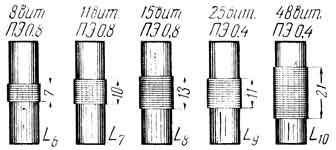
Fig.3. Drawing of inductors L6-L10
Coil L12 must be able to move relative to coil L11. The distance between them is selected experimentally. Coils L11 and L12 are enclosed in a copper or aluminum screen. At the top of the screen there is a nut (not shown in the figure) in which the ferrite core screw rotates. Using this core you can configure the L11, L12 circuit.
Fig.4. Drawing of inductors L11-L12
Transformer Tr1 is wound on a Sh15 core, the thickness of the set is 20 mm. Winding 1 contains 3000 turns of PEL 0.12 wire; winding 2 - 70 turns of PEL 0.4 wire. You can use a ready-made one - from an industrial receiver "Voronezh". The power transformer is also ready with suitable supply voltages. The rectifier must provide a current of at least 25 mA at a voltage of 230...250 V.
Setting up the receiver
Setting up the receiver is easy. The low-frequency part and the grid detector usually start working immediately. If generation does not occur when the voltage on the shielding grid of lamp L2 increases, the distance between the coils L11 and L12 should be reduced. If there is no generation in this case, it is necessary to switch the ends of the feedback winding L12 or turn it over. If generation occurs when the potentiometer R9 is in the middle position, the adjustment of the detector cascade can be considered complete.
When setting up the conversion stage, you first need to check whether the local oscillator is working. If the local oscillator is working, then when petal 8 of lamp L2 is short-circuited to the cathode, the voltage drop across R1 increases. In the absence of generation, the voltage on the screening grid L1 should be more carefully selected by changing the value of R2.
Changing the boundaries of the ranges is carried out by changing the capacitance C12-C16 and more carefully selecting the number of turns of coils L6-L10.
By turning on the 40 m range and attaching an antenna to the receiver, they try to receive some radio station. Then, by rotating the core screw L11 and adjusting the capacitor C5, the maximum reception volume is achieved.
The sound, similar to the clinking of wine glasses and glasses, coming from a box with radio tubes, was reminiscent of preparations for a celebration. Here they are, looking like Christmas tree decorations, 6Zh5P radio tubes from the 60s... Let's skip the memories. A return to the ancient conservation of radio components was prompted by viewing the comments to the post
“Detector and direct amplification VHF (FM) receivers” ,
including a circuit based on radio tubes and the design of a receiver for this range. Thus, I decided to supplement the article with the construction tube regenerative VHF receiver (87.5 - 108 MHz).
Retro science fiction, such direct amplification receivers, at such frequencies, and even on a tube, have not been made on an industrial scale! Time to go back in time and assemble a circuit in the future.
0 – V – 1, lamp detector and amplifier for telephone or speaker.
In my youth, I assembled an amateur radio station in the 28 - 29.7 MHz range at 6Zh5P, which used a receiver with a regenerative detector. I remember the design turned out great.
The desire to fly into the past was so strong that I simply decided to make a model, and only then, in the future, to arrange everything properly, and therefore I ask you to forgive me for the carelessness in the assembly. It was very interesting to find out how all this would work at FM frequencies (87.5 - 108 MHz).
Using everything I had at hand, I put together a circuit and it worked! Almost the entire receiver consists of one radio tube, and given that there are currently more than 40 radio stations operating in the FM range, the triumph of radio reception is invaluable!
 |
| Photo1. Receiver layout. |
The most difficult thing I encountered was powering the radio tube. It turned out to be several power supplies at once. The active speaker is powered from one source (12 volts), the signal level was enough for the speaker to work. A switching power supply with a constant voltage of 6 volts (twisted the twist to this rating) fed the filament. Instead of an anode, I supplied only 24 volts from two small batteries connected in series, I thought it would be enough for the detector, and indeed it was enough. In the future, there will probably be a whole topic - a small-sized switching power supply for a small lamp design. Where there will be no bulky network transformers. There was already a similar topic: “Tube amplifier power supply made from computer parts.”
 |
| Fig.1. FM radio receiver circuit. |
This is so far only a test diagram, which I drew from memory from another old radio amateur’s anthology, from which I once assembled an amateur radio station. I never found the original diagram, so you will find inaccuracies in this sketch, but this does not matter, practice has shown that the restored structure is quite functional.
Let me remind you that the detector is called regenerative because it uses positive feedback (POS), which is ensured by incomplete inclusion of the circuit to the cathode of the radio tube (to one turn in relation to the ground). Feedback is called because part of the amplified signal from the output of the amplifier (detector) is applied back to the input of the cascade. Positive connection because the phase of the return signal coincides with the phase of the input signal, which gives an increase in gain. If desired, the tap location can be selected by changing the influence of the POS or increasing the anode voltage and thereby enhancing the POS, which will affect the increase in the transmission coefficient of the detecting cascade and volume, narrowing the bandwidth and better selectivity (selectivity), and, as a negative factor, with a deeper connection will inevitably lead to distortion, hum and noise, and ultimately to self-excitation of the receiver or its transformation into a high-frequency generator.
 |
| Photo 2. Receiver layout. |
I tune the station using a tuning capacitor of 5 - 30 pF, and this is extremely inconvenient, since the entire range is filled with radio stations. It’s also good that not all 40 radio stations broadcast from one point and the receiver prefers to pick up only nearby transmitters, because its sensitivity is only 300 µV. To more accurately adjust the circuit, I use a dielectric screwdriver to slightly press on the coil turn, shifting it relative to the other so as to achieve a change in inductance, which provides additional adjustment to the radio station.
When I was convinced that everything was working, I took it all apart and stuffed the “guts” into the drawers of the table, but the next day I connected everything back together again, I was so reluctant to part with nostalgia, tune in to the station with a dielectric screwdriver, twitch my head to the beat of musical compositions. This state lasted for several days, and every day I tried to make the layout more perfect or complete for further use.
An attempt to power everything from the network brought the first failure. While the anode voltage was supplied from the batteries, there was no 50 Hz background, but as soon as the mains transformer power supply was connected, the background appeared, however, the voltage instead of 24 now increased to 40 volts. In addition to high-capacity capacitors (470 μF), it was necessary to add a PIC regulator along the power circuits to the second (shielding) grid of the radio tube. Now the adjustment is done with two knobs, since the feedback level still varies over the range, and for ease of adjustment I used a board with a variable capacitor (200 pF) from previous crafts. As the feedback decreases, the background disappears. An old coil from previous crafts, of a larger diameter (mandrel diameter 1.2 cm, wire diameter 2 mm, 4 turns of wire), was also included in the kit with the capacitor, although one turn had to be short-circuited in order to accurately fall into the range.
Design.
In the city, the receiver receives radio stations well within a radius of up to 10 kilometers, both with a whip antenna and a wire 0.75 meters long.
An additional high-frequency amplifier (UHF) is requested to reduce the influence of the antenna, which will make the tuning more stable, improve the signal-to-noise ratio, thereby increasing sensitivity. It would be nice to do UHF on a lamp too.
It’s time to finish everything, we were talking only about the regenerative detector for the FM range.
And if you make replaceable coils on connectors for this detector, then
you will get an all-wave direct amplification receiver for both AM and FM.
A week passed, and I decided to make the receiver mobile using a simple voltage converter using a single transistor.
Mobile power supply.
Purely by chance I discovered that the old KT808A transistor fits the radiator from the LED lamp. This is how a step-up voltage converter was born, in which a transistor is combined with a pulse transformer from an old computer power supply. Thus, the battery provides a filament voltage of 6 volts, and this same voltage is converted to 90 volts for the anode supply. The loaded power supply consumes 350 mA, and a current of 450 mA passes through the filament of the 6Zh5P lamp. With an anode voltage converter, the lamp design is small-sized.
Now I decided to make the entire receiver a tube one and have already tested the operation of the ULF on a 6Zh1P lamp, it works normally at a low anode voltage, and its filament current is 2 times less than that of a 6Zh5P lamp.
 |
| Installation of a 28 MHz radio station. |
Addition to comments.
If you slightly change the circuit in Fig. 1, adding two or three parts, you will get a super-regenerative detector. Yes, it is characterized by “insane” sensitivity, good selectivity in the adjacent channel, which cannot be said about “excellent sound quality”. I have not yet been able to obtain a good dynamic range from a super-regenerative detector assembled according to the circuit in Fig. 4, although for the forties of the last century one could consider that this receiver has excellent quality. But we need to remember the history of radio reception, and therefore the next step is to assemble a super-super-regenerative receiver using tubes.
 |
| Rice. 5. Tube super-regenerative FM receiver (87.5 - 108 MHz). |
Yes, by the way, about history.
I have collected and continue to collect a collection of circuits of pre-war (period 1930 - 1941) super-regenerative receivers in the VHF range (43 - 75 MHz).
In the article "Tube super-regenerative FM receiver"
I have replicated the now rarely seen super regenerator design from 1932. The same article contains a collection of circuit diagrams of super-regenerative VHF receivers for the period 1930 - 1941.
Lbvf Reply How it all started, I enter the room behind the brother, sitting naked...

In A. Balashov’s book “Magic: attracting love and happiness” it is said that...

Dream Interpretation of what you dream about Key from Monday to Tuesday Tuesday is under...