Denis Valentinovich Manturov Minister of Industry and Trade of the Russian ...

These recommendations, which represent the generalized experience of civil engineering enterprises and other industries in cleaning floors and stained-glass windows, were developed with the aim of further improving the technology of mechanized cleaning of floors and stained-glass windows.
The recommendations are intended for operators and designers of air terminals, air service agencies and other similar types of passenger buildings.
MINISTRY OF CIVIL AVIATION
State Design and Survey and Research Institute
Aeroproject
MOSCOW
These Recommendations have been developed on the basis of studies conducted by the GPI and NII GA Aeroproject jointly about Soyuzdorniya, and as a result of generalizing the experience of using rep metalizing mastics at civil aviation airports.
When compiling the Recommendations, the following documents were used: “Technical conditions TU 6-05-1816-77. Epoxy compounds of UP-5-122AT and UP-5-122AT-1 ", 1977, with changes from 1981;" Recommendations on the means in the technology of filling cracks and seams of airfield pavements ", M., GPI and NII GA Aeroproject, 1976; "Guidelines for the organization and technology of aerodrome repair without interruption of flight operation" M., GPI and NIIGA Aeroproject, 1979; "Factory rules for wire casting ESP 007502" Prague, 1971.
1.1 The performance and durability of the sealing materials used to fill the grooves of the power supply wires depend on climatic factors and on the nature of the effect of gas jets of aircraft jet engines on the coating.
1.2. The sealing material must ensure the waterproofness of the furrow and protect the cable from damage. The assessment of the suitability of the existing mastics for sealing the grooves of the power supply wires for the lights of the in-depth type "Candle-3" ID-2 was made on the basis of materials from a survey of artificial coatings and the accumulated experience of operating airfield coatings.
1.3. All work on laying the wires in the furrows and filling them with a sealing material must be carried out in dry and clear weather at an ambient temperature of at least + 5 ° С.
1.4. Furrow fillers in aerodrome pavements should not change their properties upon short-term (up to 1.5 minutes) exposure to temperatures up to + 250 ° C.
1.5. Furrow fillers must have sufficient cord grip with concrete and asphalt concrete, not crack under the influence of low temperatures and maintain their elastoplastic properties during operation.
1.6. Furrow fillers must have sufficient deformation and strength properties within the temperature range from -40 ° C to + 80 ° C, as well as resistance to the action of deicing agents.
1.7. The viability of a freshly prepared aggregate must be at least 4 hours. The sealant must be cured in no more than 7-10 days, the sealing material must not adhere to airplane pneumatics.
2.1. To fill the grooves of power supply wires in cement concrete and reinforced concrete coatings, UP-5-122AT (TU6-05-1816-87) compound and EP0KSI-15 mastic produced in Czechoslovakia are used.
The UP-5-122AT compound, produced by the domestic industry, is a product of combining the UP-5-122A modified epoxy resin, the thiokol plasticizer (GOST 12812-72), the polyethylene polyamine hardener (TU 6-02-594-75) and the UP- 606/2 ( T U 6-09-4136-75).
2.2. The curable compound UP-5-122AT is characterized by high deformability, good adhesion to concrete, sufficient water, heat and frost resistance.
Compound UP-5-122AT is a homogeneous viscous liquid of yellow or red-brown color without foreign inclusions and has the following physical and mechanical properties;
2.3. The compound should be prepared at the work site, just before filling the grooves, by mixing the components in a cold state, weighing not more 5.0 kg, because with a larger mass, homogeneous mixing cannot be achieved.
Since the compound at an air temperature above + 25 ° C quickly sets and there are difficulties in filling the grooves, then the prepared compound cannot be stored.
2.4. The dosage of the components of the UP-5-122AT compound in the field should be made by volume.
2.5. In some cases, in the absence of sealing materials based on epoxy resins in cement-concrete and reinforced concrete coatings, mastics based on a rubber-bitumen binder can be recommended for sealing the grooves of power supply wires. In this case, after cleaning the walls, the furrows are primed with a thin layer of RBV solution in gasoline in a 1: 1 ratio.
2.6. Resino-bitumen binder (TU-21-27-41-75) is produced by the industry in a finished form, it is a homogeneous mixture obtained from rubber crumb, bitumen, coumarone resin V and G, automotive oil Ak-15 and plasticizing additive (polyisobutylene P-200) or without it.
Rubber-bitumen binders are produced in three grades: RBV-25, RBV-35, RBV-50. The composition of RBV-25 is recommended for use in IV and V, RBV-35 in III and IV and RBV-50- in I and II climatic zones. Polymer bitumen mastic should be used in II f III climatic zones.
2.7. For the preparation of polymer-bitumen mastics, bitumen BND 90/130 - 100v.ch are used; divinylstyrene thermoplastic elastomer (dry matter) - 26 parts by weight; condensate "Vuktyl" - 12 wp; asbestos flour - 28 wp. and Portland cement M400 - 28 wt.
2.8. The main physical and mechanical properties of RBV and polymer-bitumen mastics are given in the table.
| Sealing material brands | Breaking strength, MPa | Relative extension, % | Adhesion to concrete, MPa | Brittleness temperature, ° C |
| BMTV-1 | 0,6 - 0,9 | |||
| RBV-25 | 0,25 - 0,50 | |||
| RBV-35 | 0,25 - 0,50 | |||
| RBV-50 | 0,25 - 0,50 |
2.9. The technology for the preparation of mastics is given in the "Recommendations for the means and technology for filling cracks and seams of airfield coverings".
2.10 Filling the grooves with RB mastic B should be carried out at a sealant temperature of 170-200 ° C using a manual joint filler developed by GPI and NII GA A e po p po ect, and in its absence - manually.
2.11. Approximate consumption of RBV mastic per 100 running meters. m furrow about 50 kg, mastic UP-5-122AT - about 25 kg. The approximate consumption of UP-5-122AT-1 mastic for fixing a single fire, depending on its design, is from 3 to 5 kg.
3.1. The cutting of the grooves of the power supply wires is carried out in accordance with the project by the DS-133 cutter. The maximum cutting depth is 80 mm.
3.2. Before laying the wires, the grooves of the grooves must be thoroughly cleaned with subsequent blowing with a jet of compressed air. The walls of the grooves before filling them with mastic should be dry. Electric wires should not come out on the surface of the covering. For this purpose, rubber rollers 5 cm long are laid on the wires every 80 cm. The grooves of the grooves must have the correct shape, without chips and cracks.
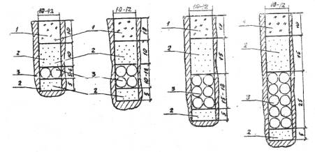
3.3. The recommended width of the groove for laying the CE-4 cable is 11 mm, for laying the KRZ cable - 13 mm. The depth of the groove to be cut is set depending on the number of wires and the applied mastic and varies from 30 to 70mm. The sequence of filling the groove from bottom to top:
sand 5mm, wires (from 2 to 8), sand 10mm, UP-5-122AT mastic;
The minimum depth of pouring the UP-5-122AT compound in cement-concrete and reinforced concrete coatings is 10 mm. The minimum depth of filling the grooves with RB mastic B in asphalt and cement concrete pavements 30 mm. In fig. Figures 1 and 2 show schemes of filling furrows in cement-concrete and asphalt-concrete pavements with various mastics.
3.4. To reduce possible swelling with mastic, RBV is first filled with 2/3 of the furrow depth, and after cooling to a temperature of 60-80 ° C, the furrow is filled completely. Excess mastic is removed with a heated scraper.
3.5. Where the grooves of the power supply wires of the in-depth type lights intersect with temperature seams, recesses from 50 to 80 mm should be made, depending on the number of wires. The wires should be embedded in PVC tubes, covered with dried and sifted sand and filled with RBV mastic. A diagram of the laying of wires at the intersection of grooves with expansion joints is shown in Fig. 3.
Rice. 1. Scheme of filling grooves in cement-concrete coatings when protecting the cable with epoxy-based mastics: I- epoxy-based mastic; 2 - fine-grained sand; 3 - cable
Note ... The diameter of the CE-4 cable is 5 mm, the KR3 cable is 6 mm.
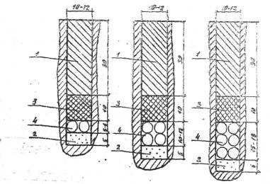
Rice. 2. Scheme for filling the grooves when protecting the power cable with RBV mastic: I- RBV mastic; 2 - fine-grained sand; 3 - oiled tourniquet; 4 - cable
Note ... The diameter of the CE-4 cable is 5 mm, the KR3 cable is 6 mm.
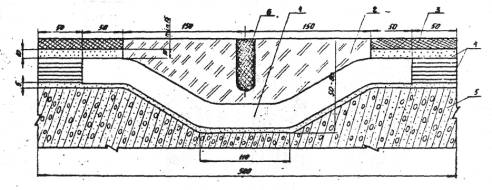
Rice. 3. Layout of wires at the intersection of the furrows with a temperature seam:
1 - perchlorovinyl tube Ø 25 or 32 mm depending from the number of wires; 2 - RBV mastic; 3 - filling mastic; 4 - sand; 5 - concrete-reinforced; 6 - expansion joint
4.1. During the preparation of mastic, it is necessary to control:
weight dosage of the components of the compound;
uniformity of mixing throughout the mastic;
heating temperature of RBV and BMTV mastics.
4.2 The heat resistance of the mastic is checked after its completion. formation by the passage of the heat engine in the mode of its operation in the winter period.
Melting and blowing of the mastic in the furrow is not allowed.
4.3. To ensure reliable sealing and protection of wires from damage, it is necessary to carry out systematic monitoring of the condition of the mastic in the furrow. In areas where mastic peeling or chipping has occurred, the destroyed area should be cleaned with subsequent filling with mastic.
5.1. The components of the compound are stored in a hermetically sealed container in an ordinary warehouse at a temperature not above + 30 ° С in conditions that ensure the safety of the product and container.
5.2 The compound is prepared immediately before use from the original components. Freshly prepared compounds cannot be stored.
5.3. The guaranteed shelf life of individual components is determined by the current normative and technical documentation and is: for modified epoxy resin - 6 months; polyethylene polyamine hardener - 6 months; accelerator brand UP-606/2 - 6 months; thiokol - 3 years.
5.4 RBV is produced by the manufacturer, transported and stored in the form of pieces weighing 10-15 kg or in paper bags weighing up to 35 kg.
5.5 During storage and transportation, the sealant must be protected from exposure to sunlight and moisture.
6.1. Uncured UP-5-122AT compound and its constituent components, through direct contact, have an irritating effect on human skin, manifested in the form of eczema and dermatitis. Therefore, all workers involved in the preparation and application of mastics must be provided with protective clothing.
6.2. All operations for the preparation of the UP-5-122AT compound should be carried out in the open air.
6.3 Spilled resin, hardener or plasticizer should be removed immediately with a dry swab, followed by rubbing the skin with alcohol and rinsing with warm water.
6.4. Components of epoxy compounds (resin, thiokol, hardener) burn when brought into a fire source. Extinguishing media include water, steam and carbon dioxide extinguishers.
At the place of production of work on heating mastics, you need to have fire extinguishing means (fire extinguisher, box with sand).
6.5. For the preparation, transportation and application of RBV mastics, it is allowed to use only serviceable mechanisms and devices.
6.6. When warming up the sealing material, it is necessary to monitor the operation of the fuel injectors.
6.7. Boilers and furnaces should be promptly cleaned of carbon deposits.
6.8. Care must be taken when pouring hot mastic from the boiler to the grouting unit.
6.9. When heating the sealing material, it is prohibited:
reheat material in boilers with open lids;
work with a faulty fuel supply system;
add molten mass to the boilers;
exceed the temperature of the heated material (180 ± 5 ° C)
6.10. If rubber-bitumen mastic gets on the open surface of the skin, it must be removed with a clean cloth moistened with gasoline or kerosene, then rinsed with water.
Occupational safety at urban construction sites and households using cranes and hoists.
Educational-methodical, practical and reference manual.
Authors: Roitman V.M., Umnyakova N.P., Chernysheva O.I.
Moscow 2005
3.1.3. Longitudinal tie-down of tower cranes.
Determination of the extreme parking of the crane (Fig. 2.1.) Is carried out in the following order:
From the extreme corners of the outer dimensions of the building from the side opposite to the tower crane, markings are made with a compass solution corresponding to the maximum outreach of the crane boom L max (Art 1 and Art. 2);
From the middle of the inner contour of the building - with a compass solution corresponding to the minimum outreach of the crane boom L min (Art. 3 and Art. 4);
From the center of gravity of the heaviest elements - with a compass solution corresponding to a certain boom reach L 1 according to the load characteristics of the crane (Art. 5 and Art. 6).
The extreme notches define the position of the center of the crane in the extreme position.
According to the found extreme parking of the crane, the length of the crane runways is determined (Fig.2.2.):
L PP = l KR + B+ 2 l BRAKE + 2 l Tup ,
where L PP- length of crane runways, m; l KR - the distance between the extreme stands of the crane, determined according to Fig.2.1., m; B- crane base, determined by reference books (Appendix A), m; l BRAKE- the value of the braking distance of the crane, taken at least 1.5 m; l Tup- the distance from the end of the rail to the dead ends, equal to 0.5 m.
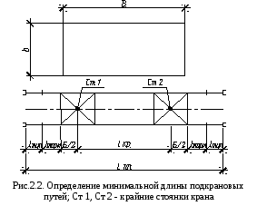
The determined length of the crane runways is adjusted upward, taking into account the multiplicity of the half-link length, i.e. 6.25 m. The minimum permissible length of the crane runways is two links (25 m).
Auditory lessons- 4 hours.
Purpose of the lesson... Acquaintance with the methodology for calculating the hazardous area of operation of assembly cranes, the acquisition of skills in the design of construction plans.
Determine the dimensions and place the construction site fence, given the compactness of the construction plan. Determine the installation site of a tower crane for the construction of a multi-storey building, calculate the danger zone. If necessary, set the limitation of the range of the erection crane.
3.1. Initial data.
Table 3.1 - Assignment for performing practical lesson No. 3
|
option |
Building dimensions, m |
Building height, m |
Maximum structure size, m |
Compactness of the construction plan |
Having the initial data on the dimensions of the facility being built, the number of cranes is selected and the crane's workplace is organized.
When choosing a crane workplace (parking), it is necessary to analyze various options for its placement and movement, as well as its technical capabilities, depending on the characteristics of the structures to be lifted and the size of the building being erected.
The number of cranes depends on the scheduled construction time and the configuration of the buildings.
For the construction of multi-storey buildings, as a rule, tower cranes are installed on one side (opposite to the exits).
The transverse connection to the building of tower cranes with a lower counterweight is determined by the dimensions of the slewing platform, increased by a distance of 0.7 m. The attachment of an attachment crane depends on the size of its support, for example, a concrete foundation, to which the crane is attached using anchor bolts; take 2.5 - 3.5 m.
Occupational safety at urban construction sites and households using cranes and hoists.
Educational-methodical, practical and reference manual.
Authors: Roitman V.M., Umnyakova N.P., Chernysheva O.I.
Moscow 2005
3.1.2. Cross linkage of cranes.
B = R max + l without (3.3)
where:
R max is the maximum turning radius of the platform (or other protruding part) of the crane (m);
Denis Valentinovich Manturov Minister of Industry and Trade of the Russian ...

Denis Manturov (born February 23, 1969, Murmansk, RSFSR, ...

, The Arbitration Court, the General Prosecutor's Office and the Federal Penitentiary Service, as well as a brief description ...